AFT Blog
Modeling Area Changes As Additional Pipe Fittings
If you have a system where there are several area changes throughout the piping, modeling every single area change and connecting pipe can become taxing and time consuming. Also, the more pipes and junctions that are in a model, the higher the complexity.
With AFT software, it is very simple to include the area change losses in the pipes themselves!
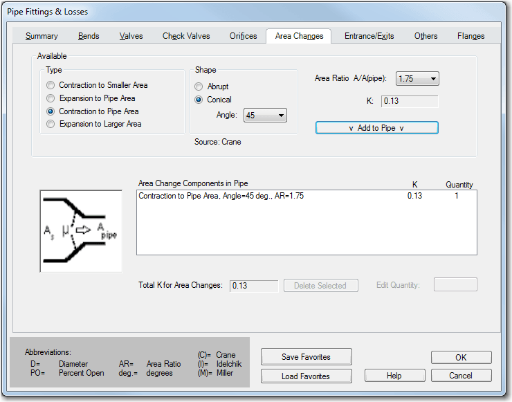
As seen in the Pipe Fittings and Losses screen shot below, there are four area change types that can be used and either abrupt or conical shapes can be modeled. The key to determining which expansion or contraction type to use depends on the location of the area change in the pipe that is being modeled and the associated area ratio.
The area change loss models in AFT Fathom were taken from Crane 1988 and all K factor relationships for area changes require an area ratio.
With modeling a physical area change junction, the area ratio is automatically determined by the size of the upstream and downstream pipes, and you can choose whether to use either the upstream, downstream or a different diameter for the basis of your area ratio.
When including the area change as an additional fitting to a pipe, you need to determine the area ratio to use ahead of time. For all contractions and expansions, the area ratio (AR) is always defined by the following relationship.
The basis area for the calculation (Apipe) is taken from the Pipe Model tab in the properties window and it is worth noting that Apipe is not arbitrary. If "A" is assumed to be a larger pipe being contracted down to the specified pipe diameter "Apipe", then the ratio will be greater than 1. However, if "A" is assumed to be smaller than the specified pipe area, then the area ratio will be less than 1. This is best illustrated by way of example.
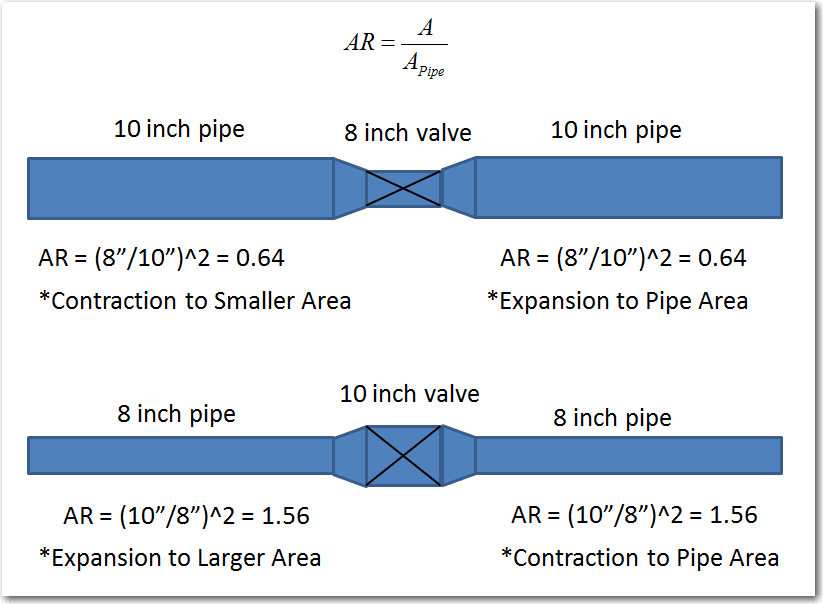
The picture below illustrates two potential cases that can be modeled where the main piping diameter is different than the diameter of a valve.
As you can see, the area ratios for the upstream and downstream pipes are the same in either case.
With the direction of flow going from left to right in both cases, the top case is a contraction – expansion while the bottom case is an expansion – contraction. The upstream pipes in both cases use a “smaller” or “larger” area change type and the downstream pipes use the “pipe” area change type.
All in all, this method is useful because in either case, two extra junctions do not have to be modeled. Also, if there was a short length of piping between the area changes and the valves, the short piping may not need to be modeled either, if you decide you want to neglect the short pipe. Thus, the equivalent losses due to the area change are still maintained in the model without the extra complexity!


Comments 7
Hi Ben,
I know I'm late for comments but nevertherless...:-)
About area changes: if I model a reducer as specific junction (big pipe inlet/upstream, small pipe outlet/downstream, Fathom will calculate flow in adjacent pipes (assumed positive for sake of example) and the reducer loss.
Now in another scenario, the flow reverses through the reducer (flows are negative), which becomes in this flow configuration an expansion. Will Fathom correctly calculate an expansion loss, with the inputs given for a reducer?
Hi Allen, no worries at all, questions welcome any time!
Anyway, that is a very good point that you have brought up. If you model an area change as an actual junction and the flow reverses, then you will see error messages that the loss factors may not be correct which is true since the loss factor relationship depends upon an assumed flow direction and upstream and downstream pipe areas.
For using area change junctions, it is easy to correct the errors by simply selecting the surrounding pipes in the flow path and using the "Reverse Pipe Direction" feature. Then your loss factors will be correct.
When you include the area changes as additional fittings and losses with the pipes as well, Fathom will not make any corrections for reverse flow, nor will there be any warnings. There would simply be reverse flow and the corrections would have to be done manually.
However, with all the above said, even with correcting the loss factors accordingly, it may not change the results that much. But it would certainly be worth doing a test to see how much it does change the results.
Hope that clarifies!
Hi Ben, a very late question to your comment.
When using rectangular ducting the area change function is not working in automatic mode.
I have to define the K factor manually.
Is there a way that AFT calculates the K factor based on the dimensions of the ducting upsteram and downstream of change area junction?
When defining the area change in "fitting & losses" AFT Arrow allows to chose different scenarios as described by you above.
This kind of opportunity I miss when using a physical change area junction.
Thank you very much.
Hi Jens, the K factors that are used for area changes are based upon cylindrical loss models. If you open the Help file and under "Junctions", you can find the "Area Change Loss Model" topic. This will provide you the K factor loss models for area changes that we are using. The conical transitions come from Crane while the abrupt comes from Idelchik. At this time, we do not have loss models built in for rectangular ducts, so the best thing to do would be to enter a user-specified K factor, or you can create your own custom component database with various K factors based upon the situation being modeled. Thanks Jens and let us know if you have any other questions.
Thank you Ben for your answer! I will then need to to a bit more manual work.
Hi Ben, I have a 30" pipe that contracts to 24" and then contracts later from 24" to 20". What would be the appropriate ARs? I assume (24/30)^2 = 0.64 for the first contraction, but is the second contraction in reference to the original pipe diameter or the diameter I'm adjusting from? So either (20/30)^2 = 0.44 or (20/24)^2 = 0.69. Thank you!
Hi Kyle,
Thanks for your question! This blog was written to help people better understand how to determine their area ratios when they are lumping the area changes into the "Fittings & Losses" tab in the Pipe Property window.
The key thing here to consider is, what is the primary diameter of the PIPE that you are actually trying to model? Let's say that the 30" and 20" pipe portions of the overall pipeline are very short, and let's assume that the 24" diameter portion of the pipeline is long. In this case, if your 30" to 24" contraction happens at the INLET of the 24" diameter pipe that is modeled in the Pipe Property window and the 24" to 20" contraction happens at the OUTLET of the 24" diameter pipe that is modeled, then this is where you would lump in TWO SEPARATE area changes into the Fittings and Losses tab.
However, if your case has a decent length of piping for the 30" section, 24" section, and 20" section, then in that case, I would recommend modeling each 30", 24", and 20" diameter pipe explicitly as separate pipes, and then use the Area Change junction to capture the transition between each pipe. When you use the area change junction, the area ratio and K factor will automatically be calculated for you based upon the upstream and downstream diameters.
Hope that helps clarify!