


AFT Blog
Welcome to the Applied Flow Technology Blog where you will find the latest news and training on how to use AFT Fathom, AFT Arrow, AFT Impulse, AFT xStream and other AFT software products.
8 minutes reading time
(1511 words)
Featured
The Opposite of Good Vibrations - Evaluating FIV, AIV, FIP Guidelines from AFT Fathom and AFT Arrow
Learn how to use AFT Fathom and AFT Arrow to help calculate the Likelihood of Failure (LOF) for Flow Induced Vibration (FIV), Acoustic Induced Vibration (AIV), and Flow Induced Pulsation (FIP) in accordance with Energy Institute Guidelines to avoid vibration induced fatigue failure.
Introduction to Vibration Induced Fatigue and Failure
Repeated vibration on a piping system can result in vibration induced fatigue and failure. Pipe failure due to vibration creates safety concerns for personnel and environmental contamination, as well as costly downtime and repairs. Despite these concerns, vibration sources and resulting fatigue are often not addressed by design standards. Instead, designers and operators often react to vibration issues rather than prevent and avoid these issues proactively.
In response to vibration concerns, the Energy Institute developed the guidelines for the avoidance of vibration induced fatigue failure in process pipework. These guidelines provide many sources of vibration for engineers to consider, many of which can be identified or modeled in an AFT application as found in Table 1.
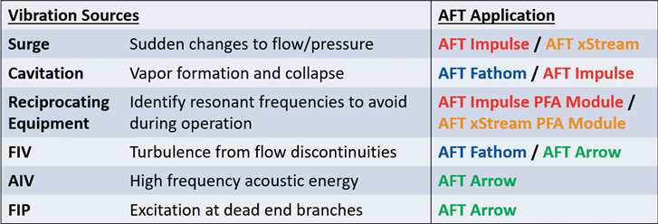
Table 1: Various vibration and pulsation sources and their relevant AFT application for modeling
These guidelines provide a structured approach to identify, assess, and correct vibration concerns through qualitative and quantitative methods. AFT has developed a spreadsheet which, in conjunction with model output and user input, can perform the recommended quantitative assessment of different vibration sources. These calculations used with the Energy Institute guidelines will help engineers identify vibration concerns in their systems.
This blog focuses on the cause and concerns of Flow Induced Vibration/Flow Induced Turbulence (FIV), Acoustic Induced Vibration/High Frequency Acoustic Excitation (AIV), and Flow Induced Pulsation/Periodic Flow Induced Excitation (FIP).
This blog explains what is required to assess each type of vibration, and references how to use AFT's vibration assessment spreadsheet with included instructions, the Excel Export Manager, and user input to determine the likelihood of failure (LOF) for a particular vibration concern.
Note to Customers:
This spreadsheet is automatically included in our latest installers. For example, at C:\AFT Products\AFT Fathom 13\Flow Induced Vibration Calculations.xlsx. If you have an older version, please email This email address is being protected from spambots. You need JavaScript enabled to view it. to request the spreadsheet.
Flow Induced Vibration / Flow Induced Turbulence (FIV)
"Flow induced vibration (FIV)" or "flow induced turbulence" describes the potential for vibration due to the turbulence of flow through a piping system. This vibration can occur in both liquid systems (modeled in AFT Fathom) and gaseous systems (modeled in AFT Arrow). This turbulence is especially concerning near discontinuities in flow, such as tees, equipment, partially closed valves, reducers, etc. In general, a more turbulent system (indicated by large Reynolds number) has a higher likelihood of vibration.
Turbulence inputs a wide band of energy, but the largest excitation occurs at low frequencies (< 100 hz). The vibration response at these low frequencies is often visible, either moving the pipe itself or its supports.
Determining the likelihood of failure
There are several factors that inform the likelihood of failure (LOF) due to flow induced vibration. These factors have been split into results exported from AFT Fathom or AFT Arrow and required user input. The export process is explained in detail in the linked instructions document.
Exported from an AFT Fathom or AFT Arrow model
- Fluid Density (ρ)
- Fluid Velocity (v)
- Pipe Internal Diameter (D,int)
- Gas Dynamic Viscosity* (µ) – Only required for gas systems
User Input
- Span Length (L,span) – The maximum length between supports
- Wall Thickness (T) – Used to determine external diameter
- Structural Natural Frequencies (fn) – Advanced only
Based on these inputs, the spreadsheet will calculate a representation of kinetic energy, a fluid viscosity factor (only for gases), the stiffness of the support arrangement, a 'Flow Induced Vibration Factor', and finally the likelihood of failure (LOF). The calculated LOF should be used with the Energy Institute guidelines to determine the appropriate corrective actions, if necessary.
Acoustic Induced Vibration / High Frequency Acoustic Excitation (AIV)
"Acoustic induced vibration (AIV)" or "high frequency acoustic excitation" occurs in gas systems around high pressure drop components like control valves, relief valves, restrictions, branches, etc. The sudden drop in pressure expands the fluid which creates turbulence, high velocities, noise, and high levels of high frequency acoustic energy in the range of 500-2000 hz. At these high frequencies, the vibration causes local pipe wall flexure which creates significant stress at circumferential discontinuities. Failures due to AIV can occur in hours or minutes due to the high frequency. These gas systems would be modeled in AFT Arrow.
Determining the likelihood of failure
Acoustic induced vibration depends on conditions surrounding the pressure reducing device, as well as user input specific to the source of vibration and circumferential discontinuity of concern.
Source – The high-pressure loss component (e.g. relief valves, control valves, restrictions)
- Upstream pressure of device (P1)
- Downstream pressure of device (P2)
- Upstream temperature of device (Te)
- Mass flowrate (W)
- Low noise trim component
- Molecular weight (MW)
Discontinuity – area of concern where the system is likely to fail (e.g. small bore connections, welds at tees, supports)
Exported from AFT Arrow model
- Main line internal diameter (D,int)
- Branch external diameter (d,ext)
- Distance from source to discontinuity (L,dis)
- Whether piping material is duplex
- Wall thickness of main line (T)
- Whether discontinuity is a weldolet fitting
These inputs are used to calculate a sound power level at the source, which is then modified depending on the conditions of the discontinuity. Since one source can interact with multiple discontinuities, or one discontinuity can be exposed to multiple sources, it is important to consider the combination of source/discontinuity. Corrective actions should be considered if the LOF calculated at the discontinuity is equal to one.
Flow Induced Pulsation / Periodic Flow Induced Excitation (FIP)
"Flow Induced Pulsation (FIP)" or "Periodic Flow Induced Excitation" occurs in gas systems at 'dead leg' branches, common at relief lines and closed recycle lines. Flow past the dead leg branch is analogous to blowing across the top of a bottle and hearing a tonal response. Pressure pulsation can occur if the frequency of the flow excitation coincides with the acoustic natural frequency of the branch. The natural frequency of the branch can be impacted by the fluid's pressure, temperature, and molecular weight. Like the bottle example, it is not necessarily the highest flowrate which is most concerning. A sensitivity analysis should be performed for the expected range of operating conditions. These gaseous systems would be modeled in AFT Arrow.
Determining the likelihood of failure
Unlike Flow Induced Vibration and Acoustic Induced Vibration, likelihood of failure from Flow Induced Pulsation can be determined exclusively from AFT Arrow output. Multiple dead leg branches can be evaluated from a single model's output.
Exported from AFT Arrow model- Sonic velocity at branch point (c)
- Branch internal diameter (d,int)
- Main line internal diameter (D,int)
- Length of branch (L,branch)
- Reynolds number at branch (Re)
- Velocity at branch (v)
- Static gas density in main line (ρ)
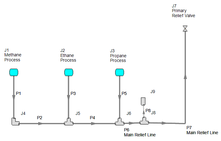
Workflow Example: Flow Induced Pulsation
Below is an example AFT Arrow model with a dead leg branch that could create flow induced pulsation.
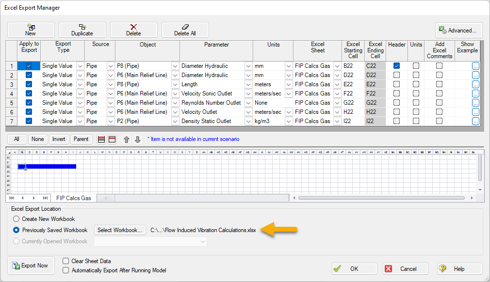
From this model, we can export the necessary information from the main line and branch line to perform our Likelihood of Failure calculation in the provided spreadsheet. In the Excel Export Manager (File>Excel Export Manager>Open…), we can specify the necessary output as found below and consistent with the included instructions document.

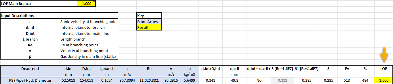
After we run the model for results, we can export our output from File>Excel Export Manager>Export Now. This should put the data in the correct place in our spreadsheet for our calculations to reference. While FIP does not require any user input, the spreadsheet will highlight the necessary user input to perform the other calculations. Below is our output results, and the calculated Likelihood of Failure for our main line and branch. The Energy Institute Guidelines should be referenced for further instruction such as corrective actions, which can then be checked in the spreadsheet.
Other Resources
If you are curious to see more of the process in detail, or more detailed explanation of FIV and AIV, check out our recent FIV Webinar and AIV Webinar. The Energy Institute Guidelines also provide essential insight into the analysis process, outlining the vibration assessment process and where the provided spreadsheet can help perform the quantitative analysis.
Comments