


AFT Blog
Welcome to the Applied Flow Technology Blog where you will find the latest news and training on how to use AFT Fathom, AFT Arrow, AFT Impulse, AFT xStream and other AFT software products.
7 minutes reading time
(1386 words)
Don't throw a fit over your Fitting K Factors - Part 1: Fittings & Losses in AFT Fathom
AFT Fathom, AFT Arrow, AFT Impulse, and AFT xStream all have a tab in the Pipe Properties window called "Fittings & Losses" which allows users to quickly specify K factors for components within a pipeline such as valves, elbows, and area changes. The Fittings & Losses allow you to simplify your model and avoid workspace clutter by integrating the K factor data into the pipe properties instead of drawing each junction on the workspace. However, this feature should be implemented differently depending on which AFT application you are using. In Part 1 of this two part blog series, we will discuss how to use Fittings & Losses in AFT Fathom. Special considerations for Fittings & Losses in AFT Arrow, Impulse, and xStream will be covered in Part 2 at a later date.
When should I use the Fittings & Losses feature?
Generally, the Fittings & Losses feature should be used when you want to simplify a model, such that instead of using a junction icon on the workspace to represent a K factor, you would incorporate the loss into the pipe properties. For example, say you have a pipe in your system that snakes its way around multiple rooms/floors in a building and has 10 different 90 degree bends. Instead of drawing the 10 bend junctions and 12 connecting pipes you could combine the loss information into the Fittings & Losses of a single pipe whose length equals the total length of all 12 pipes. Or maybe you have an expansion joint at the end of your pipe because it is connecting to a valve or component that has a larger nominal size compared to the pipe. You can incorporate this expansion into the Fittings & Losses instead of drawing a separate area change junction and additional pipe.
Something to consider is that Fittings & Losses won't work for alternate loss models like resistance curves or Cv values. If you want to use a loss model other than a K factor you should use a dedicated junction. Furthermore, Fittings & Losses should only be used on components that do not change state during the simulation or across different scenarios in your model.
Does using the Fittings & Losses feature instead of a junction affect results?
In AFT Fathom the results such as flowrate, velocity, and total pressure drop will be identical when using Fittings & Losses versus drawing the junctions individually on the workspace. When performing hydraulic calculations, the solver will create a total resistance in a unique flow path that includes friction and losses from junctions. It does not matter if the K factors are specified inside a pipe using Fittings & Losses, or separate junctions in the flow path – so long as the value of the K factors are identical. For AFT Arrow, Impulse, and xStream it gets more complicated, and as such will be discussed in Part 2. Furthermore, if you are interested in knowing the pressure at the inlet or outlet of a component, you will need to use a junction because the Fittings & Losses distribute the pressure loss over the entire pipe instead of applying it at a single point.
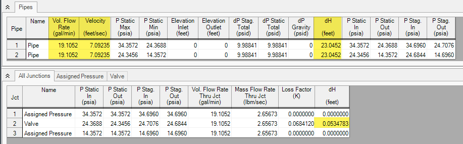
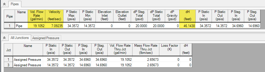
Consider the example below where one scenario has a valve junction and two pipes versus another scenario that has one pipe with a valve loss added to the Fittings & Losses. Valve J2 is a 100% open Ball valve from the Crane handbook source. The boundary conditions are 40 psig on the upstream side, and 0 psig on the downstream side, with 1 inch Steel – ANSI pipes carrying water at 60 degF. The results for the first scenario with a valve junction show that the flowrate is 19.12 gpm, velocity is 7.09 ft/s, and total head loss is 46.15 ft (P1+P2 head loss + valve head loss; 23.05*2 + 0.05 ft). The results for the second scenario with Fittings & Losses are equivalent for flowrate and velocity, and within rounding error for the head loss of 46.14 feet.
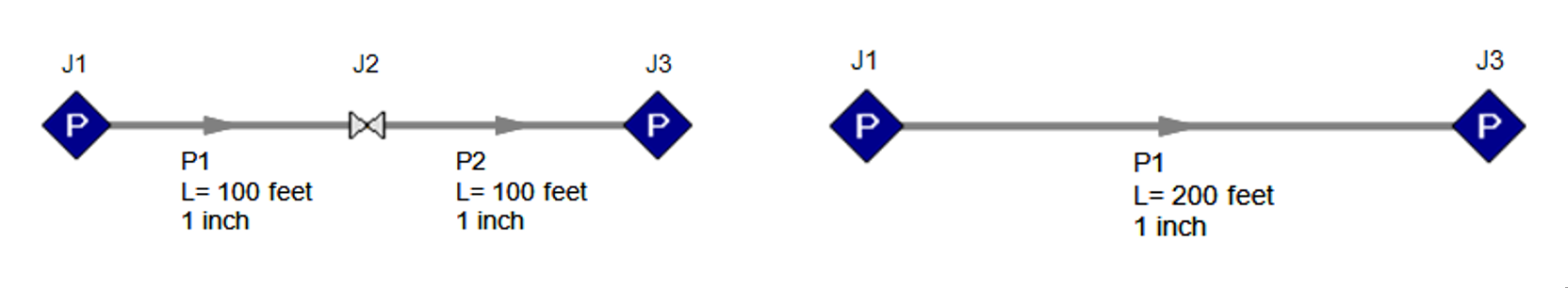
Results for scenario with valve junction (left):
Results for scenario with valve loss added in the Fittings & Losses (right):
How do I add a K factor to the Fittings & Losses?
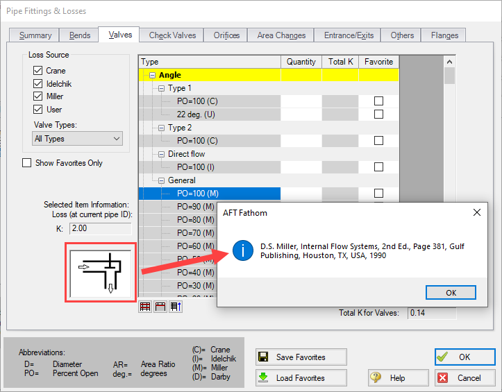
A pipe material/size must be defined before being able to use Fittings & Losses. When inside the Pipe Properties window of a defined pipe, click on the Fittings & Losses tab. From within the Fittings & Losses tab, you can click Specify Fittings & Losses from the lower right corner. Then, navigate the tabs on the top of the Pipe Fittings & Losses window to find the type of component you wish to specify. The components will be organized into sections for different valve types, bend angles, etc. Simply enter a quantity for the components of interest and the total K factor will be summed up automatically.
Note: if you have the equivalent lengths method enabled, the list of components will look different, and the data is sourced from the NFPA 13 standard.
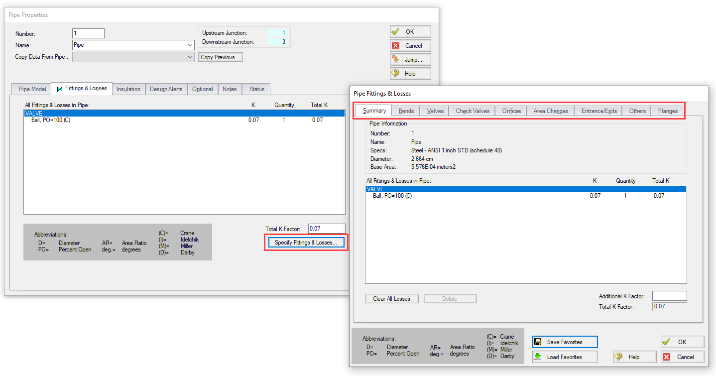
By default, our applications contain library data for different types of components that have been collected from sources such as Crane, Idelchik, Miller, and Darby. You can tell which source the K factor is from because the name will end with parentheses enclosing the first letter of the author's name – (C), (I), (M), or (D).
Pro Tip: you can double click on the picture graphic of the component in the bottom left of the window to see the full reference information including the page number that the data came from.
Most of the handbook data is based on nominal pipe size, usually for a common material such as commercial steel with turbulent flow of water. It is always preferable to use a K factor from a vendor datasheet because it matches your exact diameter and material, but if this information is unavailable or you don't have a specific component selected, the default Fittings & Losses can provide an initial estimate. You can add your own Fittings & Losses components which may be useful if you find yourself reusing the same vendor component multiple times in a system or between projects/models.
To add your own components, go to the Library menu and click Edit Fittings & Losses (versions prior to Fathom 12 used 'Databases' instead of 'Libraries'). Then click Create New Loss Item and define your component type and K factor. You can also use the Import button to import this data if you have a .csv file with the correct formatting. This can help keep your vendor information organized in separate Excel files and easily share between colleagues. See our Help File page on the Fittings & Losses Library for more information.
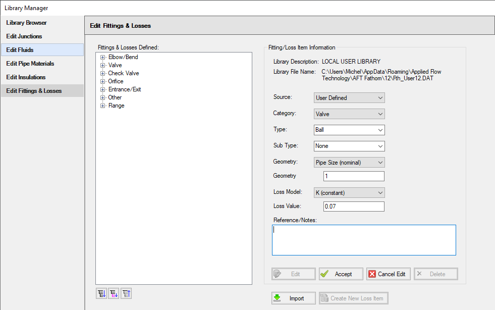
User defined Fittings & Losses will display a "(U)" at the end of the name in the lists. You can filter the lists to see only your user defined components from your local user library if desired.

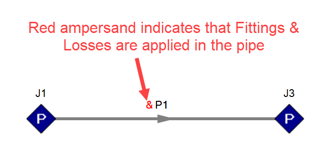
Pipes that have Fittings & Losses specified will display a red ampersand symbol on the workspace.
Potential Sources of Error
If you are using custom component losses that you added with the Library Manager and change your pipe material/size, the K factors will not be updated automatically. Don't forget to update your Fittings & Losses with new vendor data for the new nominal size components.
Furthermore, when area changes are modeled with Fittings & Losses, Fathom does not account for the fact that the velocity will be changed due to the different diameter. The hydraulic calculations use the velocity that corresponds with the pipe inner diameter, and the area change merely represents a K factor.
Summary
In conclusion, Fittings & Losses can be a useful way to simplify your model by incorporating simple K factors into a pipe's properties. Fathom's default libraries contain many component losses gathered from handbook data by Crane, Idelchik, Miller, and Darby. Furthermore, you can easily add or import your own vendor component data using the Library Manager. For more information, visit our Help Site page on Fittings & Losses.
Comments