AFT Blog
Steam Piping in Nuclear Power Plants Is Not As Safe As Commonly Believed
As if we all need something else to worry about, right? But I am afraid it is true. The concern stems from how fast steam acoustic waves steepen as they transmit through a system. This steepening causes transient forces on the steam piping much higher than conventional methods predict.
When I was beta testing AFT's latest software product, AFT xStream, in early 2021, I came across something startling. And I quickly realized that nuclear power plants are not as safe as believed.
Other researchers starting in 2014 have similarly reported higher than expected forces, but they could not explain the cause. Without a good physical explanation, their research was not adopted by industry. However, last year I and my colleagues at AFT confirmed these higher-than-predicted forces. Most importantly, we can now explain the cause using physics and theory.
There is a long version of the story and a short version. The long version of the story is given in a paper I presented today at the ASME Pressure Vessels and Piping Conference in Las Vegas – see "A Critique of Steam Hammer Load Analysis Methods". The short version of the story I will relate below.
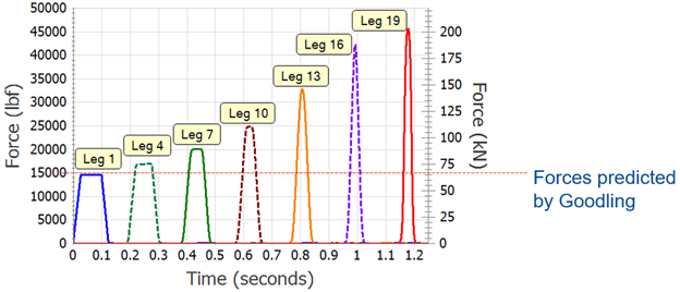
The paper presents Figure 1 below where you can see that the peak forces in the paper's example can be over 3 times greater than the Goodling Method predicts. Goodling is the common method used to estimate pipe forces in power plant steam piping, reducing the peak predicted force depending on the pipe's length.
Until AFT xStream became commercially available in April 2021, there were no commercial software tools capable of calculating the forces in Figure 1. Now there is.
The forces in Figure 1 are so much higher than Goodling because Goodling overlooked something, and he had some misconceptions about steam wave speed and steam wave propagation.
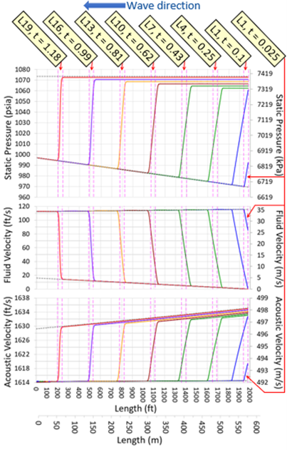
In short, when a turbine stop valve (TSV) closes rapidly (as it must in order to protect the turbine), it generates a family of waves. It can be shown with physics and theory that the back of the wave family travels faster than the front of the wave. As the back catches the front, the wave steepens.
As the wave steepens, it can more easily fit inside a shorter pipe run. This means the wave exerts a greater force on the pipe section than a less steep wave.
Now, it has been known by others that this happens, but the speed at which the steepening happens has been significantly underestimated. This means the wave steepens much faster than anyone thought possible, resulting in higher forces than predicted.
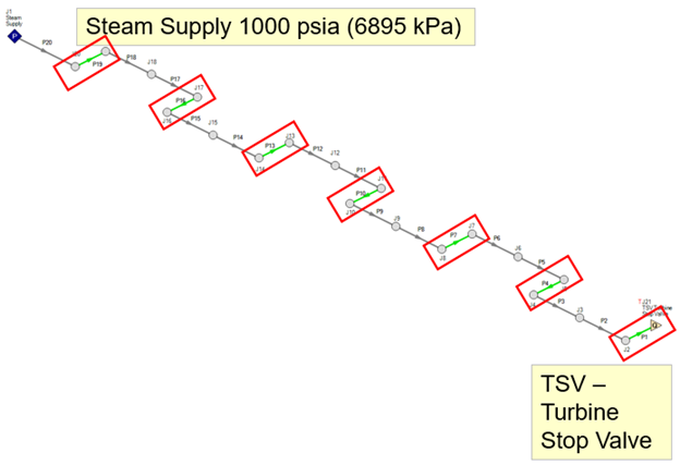
Figure 2 below shows the example pipe system. Figure 3 below shows the how the pressure wave steepens as it moves from right to left, fitting more of the wave within the same pipe length. This steepening wave causes the high forces in Figure 1.
What does the paper recommend the world should do about this startling discovery? We recommend that literally all nuclear power plants (and fossil plants, for that matter) should recalculate the forces on their installed piping. Where needed, stronger supports may be necessary. We also recommend that all future such calculations stop using the Goodling Method and use a good alternative (such as AFT xStream) in order to obtain a safer design.
For good measure, I presented a second paper at the same conference called "Improved Method of Estimating Steam Hammer Loads". This method provides a quick and dirty estimate of pipe loads that is much better and more conservative than the Goodling Method.
With any luck, these proposed methods will catch on and steam piping in the nuclear industry and beyond will be safer because of it.


Comments