


AFT Blog
Welcome to the Applied Flow Technology Blog where you will find the latest news and training on how to use AFT Fathom, AFT Arrow, AFT Impulse, AFT xStream and other AFT software products.
6 minutes reading time
(1233 words)
Awesome Annotation Tool Additions
The Annotation Tool has new shapes and customization options which will help you organize, markup, comment, and effectively present your models when using the new versions of Fathom 13, Arrow 10, Impulse 10, and xStream 3. In addition to the pre-existing rectangles and ellipses, you can now add diamonds, pentagons, hexagons, octagons, clouds, triangles, and lines (Figure 1). Each annotation can be customized with text, colors, borders, and thicknesses. In this blog I will showcase some of my favorite additions and review some useful settings.
After selecting a shape from the Annotation Tool, such as the cloud, you can click and drag your cursor across the Workspace to create the object the same way as you would have done in previous versions with the old Annotation Tool. However, the Annotation Properties will now open in the Quick Access Panel (Figure 2). The Annotation Properties can also be opened later by double-clicking on the annotation.
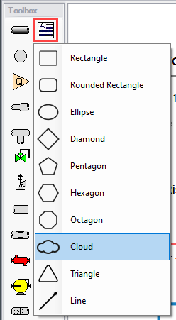
Figure 1: Different shapes available in the Annotation Tool
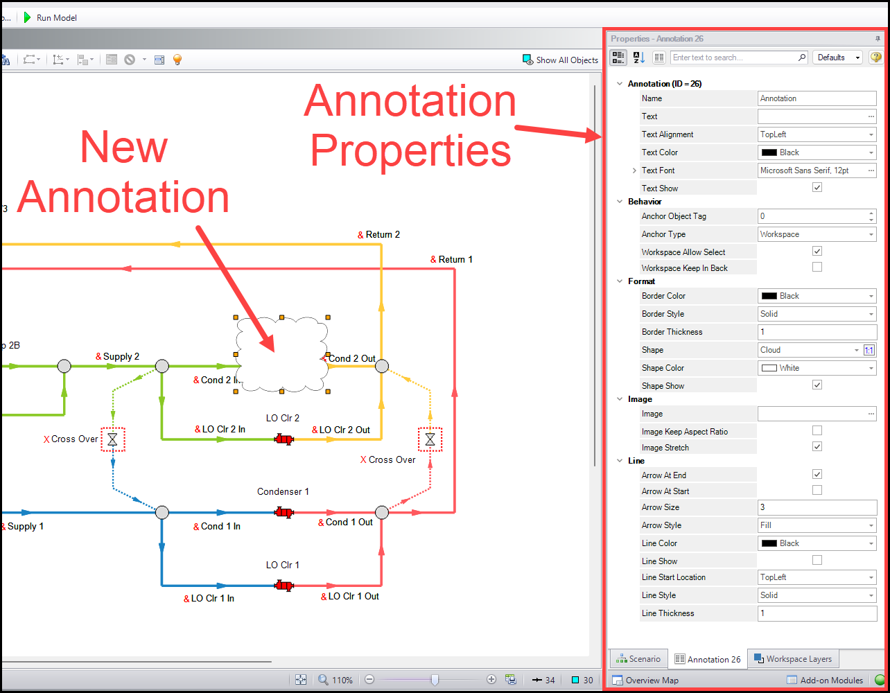
Figure 2: Annotation Properties in the Quick Access Panel
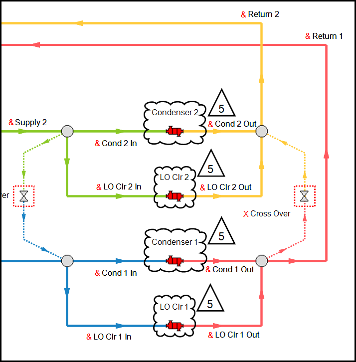
Figure 3: Example of revision markup that mimics a P&ID
Mimic Revision Notes from Piping & Instrumentation Drawings (P&IDs)
Figure 3 shows an example of how you can recreate markup in the style of a Piping & Instrumentation Drawing (P&ID) where the cloud shapes outline a piece of equipment which has a corresponding comment number in a triangle. For the cloud shapes I like to adjust the Border Thickness to make the shape more noticeable. I also like to change the Shape Color to the Transparent option (found on the "Web" color palette). Under the Behavior section, the "Workspace Allow Select" option controls whether or not the annotation is included in selections you make by clicking and dragging your cursor over the Workspace, or by simply clicking the annotation. I like to start with the setting enabled. Disabling the option will make it such that only the pipes and junctions get selected when clicking and dragging. It will also prevent you from single-clicking the annotation on the Workspace. This can be useful if you need to create selections for the Global Edit Tool or for creating graphs from the Workspace. If you need to re-open the Annotation Properties, you can always double-click the annotation and re-enable the option (despite not being able to select it with single-click).
For the triangle shapes I like to change the same Border Thickness and Shape Color settings mentioned previously. In addition, you can enter text such as a revision number. I personally find that the "Top Center" Text Alignment option works best for small triangles, otherwise "Middle Center" works well for larger shapes. Furthermore, under the Format section and next to the Shape option, there is a button that will set the aspect ratio to be 1:1 which can be used to make perfect squares or nice looking triangles (Figure 4).
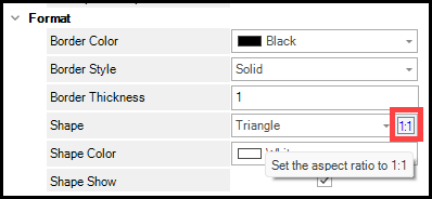
Figure 4: Button to set the aspect ratio to 1:1
Reminder: Scenario-specific notes can be input into the Notes section underneath the Scenario Manager in the Quick Access Panel. This is where you could put your enumerated comments.
Outline Areas in Your Model
For simple areas a rectangle can be created to represent different buildings in your model such as a pump station, campus building, etc. The "Workspace Keep In Back" option will place the annotation behind the pipes and junctions such that they don't overlap. This is especially useful if you have a Shape Color that would otherwise cover the pipes and junctions. Combining this with disabling the "Workspace Allow Select" setting is my go-to configuration for outlined areas.
Lines and arrows can be used in a myriad of ways. The default line annotation will have an arrow on one end which can be disabled in the Annotation Properties under the Line section. The Line Style and Line Thickness can be adjusted to create a dashed appearance such as in Figure 6 where multiple lines were drawn to create a complex outline of a pump station. When a line annotation is selected, you will notice that each end has a green dot which can be used to reposition the end points. The larger green dot corresponds to the start of the line and the smaller green dot is the end (useful to know which end is which when modifying the "Arrow At End" or "Arrow At Start" settings).
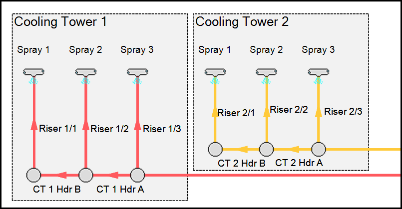
Figure 5: Enabling the “Workspace Keep In Back” option makes it easy to outline buildings
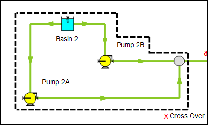
Figure 6: Example of multiple lines creating an outline of an area
Tip: Holding the SHIFT key while repositioning an end point will snap the line to various angles at 15 degree increments which is useful to draw perfectly vertical or horizontal lines.
Scenario-Specific Annotations
To avoid confusion, I put scenario-specific notes about the operating case or general purpose of the scenario in the Notes section under the Scenario Manager instead of creating a text annotation. I do this because annotations will be drawn on all active Workspace Layers (with the active pencil icon next to them). If I need to create other scenario-specific annotations, I use the following procedure:
- Duplicate the All Objects Layer from the Workspace Layers in the Quick Access Panel and name it "All Objects Layer - No Annotations".
- Ensure that the duplicated layer is ordered directly above the original All Objects Layer and that the pencil icon is disabled.
- Hide the original All Objects Layer.
- Open the Layer Settings for "All Objects Layer - No Annotations" and click the "Show/Hide Annotations" item.
- Toggle the visibility off for all annotations using the eye icons.
- Create a new layer and name it "Scenario 1 Annotations", then disable the pencil icon.
- Open the Layer Settings for "Scenario 1 Annotations" and enable the visibility of the desired annotations from the Show/Hide Annotations item.
- Create a new Layer Preset and name it "Scenario 1 Annotations" and click the link icon under the Link Scenario column in the Quick Access Panel.
- Repeat steps #6-8 for the next scenario but use "Scenario 2" for the name, and so on for the number of scenarios.
- If I need to add pipes and junctions to the model, I enable the pencil icon on the "All Objects Layer - No Annotations", then disable the pencil when I am done.
- If I need to add new annotations to the model, I enable the pencil icon on any layers I want the annotation to be displayed on, create the annotations, then disable the pencil from the layers I had enabled it on, and finally click Update for any applicable Layer Presets.
Now every time Scenario 1 is loaded the linked "Scenario 1 Annotations" Layer Preset will apply and display the selected annotations from Step #7. When Scenario 2 is loaded the linked "Scenario 2 Annotations" Layer Preset is applied.
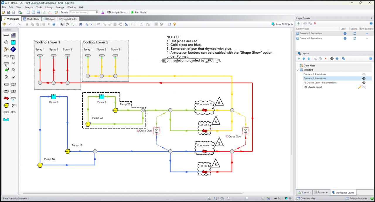
Figure 7: Scenario 1 Layer Presets Loaded
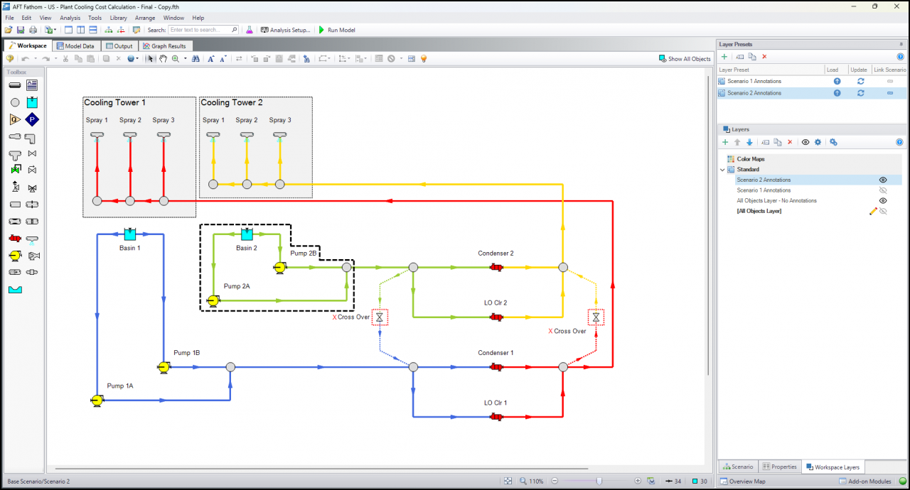
Figure 8: Scenario 2 Layer Presets Loaded
More information regarding Annotations and Workspace Layers can be found in our documentation.
Comments