AFT Blog
Compressor Maps
A Compressor Map in AFT Arrow allows you to more accurately model the full range of operating conditions for a Centrifugal Compressor junction. AFT recognized the need for this specific feature from customers via support requests and consulting projects. Well, good news…this capability is here! The feature was designed with the engineering design process in mind. AFT engineers even consulted industry experts during development to ensure it is a valuable addition to our powerful suite of compressible flow software.
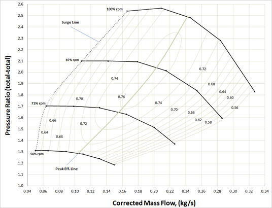
What is a Compressor Map?Compressors operating at a fixed speed are typically characterized by a Compressor Curve that relates the mass or volumetric flowrate to the compression ratio or rise in pressure/isentropic head. A Compressor Map is a family or collection of these curves for various speeds. However, Compressor Maps typically relate a corrected or non-dimensional mass flowrate on the x-axis to a pressure ratio on the y-axis. Furthermore, the speed is usually a corrected or non-dimensional speed. The boundaries of the Compressor Map define an entire range of possible operation. The left boundary is called the Surge Line, and the right boundary is called the Stall Line. These are limits that should be avoided, and Arrow has built-in Warnings that will be displayed if you are operating outside these boundaries of the Compressor Map.
Benefits of Using a Compressor Map
- Create alternate scenarios of the model faster
- Arrow linearly interpolates between the entered curves to find the operating point conditions
- Account for different inlet temperatures and pressures
- Input manufacturer data into Arrow more easily
The main benefit of using a Compressor Map is that you can create alternate scenarios of the model faster. You front-load your work by entering the various curves at the start of your project. You can even consider saving your compressor junction to a Library for repeated use in the future on other projects. After that, you can play around with different scenarios to your heart's content, and Arrow will automatically calculate the new operating point. Arrow will linearly interpolate between the curves you entered to find the exact conditions. Furthermore, it will be more straightforward to translate the manufacturer data directly into Arrow, and the model will be able to account for inlet temperatures and pressures that differ from the manufacturer test conditions.
Limitations of the Compressor Map
- The working fluid of the AFT Arrow model must be the same as the fluid used by the manufacturer when developing the Compressor Map
- The units must be provided in non-dimensional or corrected mass flowrate vs pressure ratio
How to Add a Compressor Map
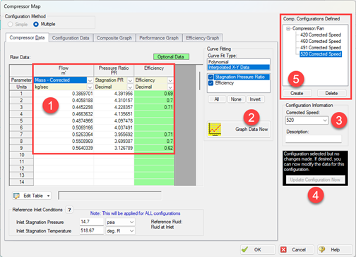
Open the Compressor Properties window, select the Centrifugal Compressor option, and select the radio button for Compressor Map. Then, click Enter Curve Data:
- Enter the data for one of the curves and select the appropriate units from the column headers
- Click Graph Data Now (if you are using a polynomial curve fit, ensure that the curve fit closely matches the data)
- Enter the corrected or non-dimensional speed
- Click Update Configuration Now
- Click Create and repeat the process for the next curve
Once you are finished entering the different curves, enter the Reference Inlet Conditions from the manufacturer and click OK to close the Compressor Map window. Finally, enter the Rated Speed for the current scenario on the Compressor Properties window. The Speed dropdown menu can be used to visually display the different curves but does not act as input for the model. The Arrow Solver will reference the Rated Speed field and the Compressor Map data that was input in the calculations.
Additional Resources
We are excited for you to start taking advantage of this new feature. Visit the AFT Arrow documentation page for further reading and features. You may also be interested in our recent blog about New Features in Arrow and xStream.


Comments