AFT Blog
Reaching Equilibrium: System Energy Balance in AFT Fathom and AFT Arrow
AFT Fathom and AFT Arrow both have the powerful ability to model heat transfer in pipes and heat exchangers, allowing you to represent these critical features of temperature-sensitive systems in your hydraulic model. However, without being able to see the affect heat transfer has on an entire system these features would be of limited usefulness.
One of the most powerful aspects of AFT’s implementation of heat transfer is that energy is balanced across the entire system. For example, you can observe changes in pump or control valve operation when adding heat transfer to a remote part of a system.
Looking at the system below, it is straightforward to understand what the overall temperature behavior will be – the heat exchanger adds a large amount of energy all at once and the pipes slowly lose energy to the environment.

The thermal behavior of such a non-branching system could be solved by hand or with a program like Excel. But what happens if we add some additional complexity? We add a second heat exchanger and let some amount of flow through it.

We know the temperature still decreases along the pipes due to convection, and increases across the heaters. But what happens when the flows rejoin? All we can say for sure is that the temperature will settle somewhere between the two stream’s temperatures. If we knew the system hydraulics, this would be relatively easy to calculate by hand.
Unfortunately, changes in fluid temperature also change the fluid’s viscosity and density, thus changing the hydraulic behavior. There is no way to separate the two problems and they must be solved in parallel, making this system much harder to solve even with a well-developed spreadsheet calculator.
Hand calculations quickly become untenable when the system becomes more complex.
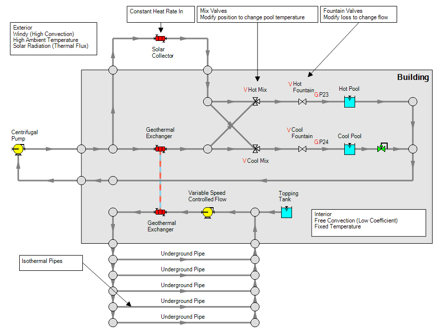
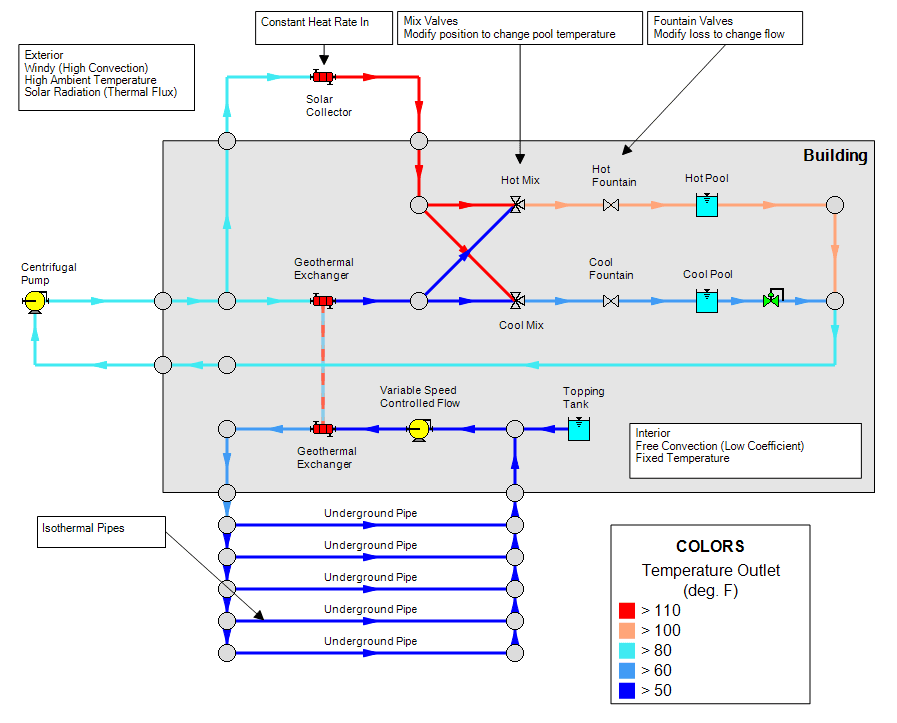
Below is a model of just such a system. A small resort is willing to commit significant upfront costs to build two eco-friendly temperature-controlled pools. The water will be heated with a large rooftop solar collector will be built, and a closed geothermal loop will be included to cool the water. The cold and hot streams are then mixed to the appropriate temperature and delivered at the necessary flow rates for the decorative but functional fountains.

The model includes:
- Closed thermal loops - the pools balance energy, meaning their temperature will change
- Multiple points of branching and combining flow
- A variety of thermal models
- A thermally linked counter-flow heat exchanger
- Convective Heat Transfer and Heat Flux – the exterior pipes are highly affected by convection and solar radiation, whereas the interior pipes are affected mostly by free convection
- Isothermal – the underground pipes which are assumed to come to the same temperature as the surrounding earth due to their length
- Specified Heat Rate In Constant heat exchanger
- Two centrifugal pumps – one of which has a variable speed control
- On top of the above, we are asking AFT Fathom to calculate the positions of 4 valves with Goal Seek & Control to obtain the desired flowrate and temperatures
As you can imagine, this would be an extremely difficult task without an iterative solver like AFT Fathom. In fact, it is difficult even for AFT Fathom when compared to the typical model – it takes careful configuration and several thousand iterations when many models are solved in hundreds or even just dozens of iterations.

AFT Fathom can tackle this problem because it balances energy system-wide. In one solver “pass” AFT Fathom iterates to find balanced pressure, flow, and temperature solutions. Each of these components affects the others, so all three must be iterated on repeatedly. During the temperature iteration, temperatures are updated to conform not only to the individual thermal models at pipes or heat exchangers, but also at every branch or combination of flow. The total amount of energy entering a branch must equal the energy leaving:
![]()
By iterating on temperature to enforce this requirement for every branch, a system wide energy balance is obtained.
With the ability to model multiple types of heat transfer in pipes or heat exhangers - as described in Erin's Heat Transfer in Pipes and Abby's Heat Transfer in Heat Exchangers blogs - along with the system energy balance, the resort can directly model the thermal behavior of their system and the positions of valves necessary to reach target temperatures. Even with an otherwise fully-featured hydraulic solver this would be a challenging problem without the inclusion of energy balance!


Comments 2
boa tarde,
estou usando o programa e não consigo fazer o balanço no tanque
Hi Alan,
We would like to help get your model up and running - if you send your model along with some more details about the problem to [email protected] we would be happy to address your question.