AFT Blog
Know Your Pump and System Curves - Part 1
AFT Fathom can easily generate a pump and system curve for your piping system. Creating a pump and system curve for a simple system with a single flow path and no control features is an easy and typically well-understood process. However, as piping systems are quite complicated with lots of branch points, control features, and dynamic interactions, creating a useful system curve can quickly become a common source of confusion. This three-part blog series is going to help clarify concepts regarding pump and system curves to better understand them.
This Part 1 blog will discuss the basics of what pump and system curves are and how they can be generated in AFT Fathom. I will start by describing the main parts of a pump and system curve and what it represents followed by a simple example for illustration. The system curve impacts from valves and control valves will be addressed. For part 2, I will discuss a more complicated system where there are multiple branch points in a system to illustrate additional system curve complexities that can exist and show how the system curve can change over time. Multiple systemc curves can exist in a system, especially when there are multiple pumps present and I will demonstrate these aspects as well. Then in part 3, I will focus on how pump and system curves are generated for multiple pumps in parallel or series. Sometimes, adding multiple pumps in parallel will not result in producing more flow and I will discuss how to understand your system curve in order to know when addtional parallel pumps will be beneficial or not.
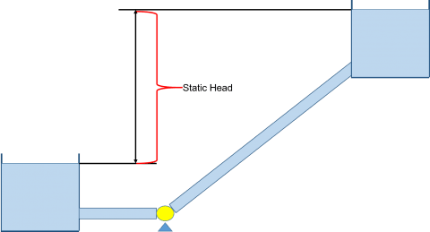
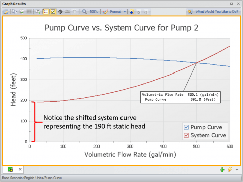
In general, a pump is used to overcome frictional head loss in piping systems as well as system elevation changes between system boundaries (i.e., static head). The term "Static Head" is represented by changes in elevation between supply and discharge reservoirs, like the system shown in Figure 1, and/or pressure differences for the case where system supply and discharge tanks may be pressurized. A system curve, as shown in Figure 2, is a graphical representation of the pump head that is required to move fluid through a piping system at various flow rates. The system curve helps quantify the resistance in a system due to friction and elevation change over the range of flows. When there are no control features in the system, such as flow control valves, then the pump and system curves will intersect at the operating flow rate.
I want to point out that a system curve is developed with reference to a specific location in a system. Therefore, multiple system curves can exist for a system and this is something that can lead to potential system curve confusion. Typically, a system curve is going to be developed with reference to a pump in a system because the pump is what will generate the necessary pressure required to overcome the system resistance at various flow rates. Stay tuned for part 2 of this blog series and I will address this concept further.
An example of what a pump and system curve might look like for Figure 1 could be that shown in Figure 2. As you can see, the system curve is shifted upwards and the shifted amount represents the static head, or elevation change that needs to be overcome by the pump in order to start generating any flow at all. The shape of the curve itself represents the frictional resistance in the system that needs to be overcame due to losses. The curves will intersect at the operating point of the system.
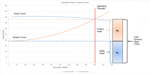
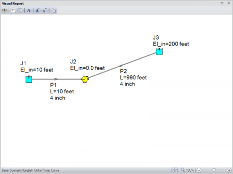
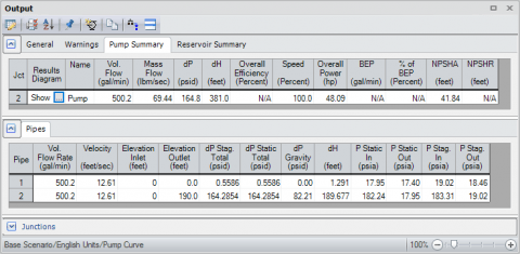
Figure 3 is an AFT Fathom model of the simple system shown in Figure 1 where water is pumped up a 200 ft (61 m) elevation over about 1000 ft (305 m) of pipe (10 ft suction + 990 ft discharge) (3 m suction + 302 m) and a pump curve has been entered for the pump. Upon review of the results in Figure 4, the total piping head loss due to friction is about 191 ft (58.2 m) (1.291 ft + 189.677 ft) (0.393 m + 57.8 m) and the static head is equal to 190 ft (58 m) (200 ft discharge reservoir liquid surface elevation - 10 ft supply reservoir liquid surface elevation) (61 m discharge reservoir liquid surface elevation - 3 m supply reservoir liquid surface elevation). Therefore, the total pump head that is required in order to overcome the 191 ft (58.2 m) of frictional resistance and 190 ft (58 m) static head is about 381 ft (116 m), which is exactly what the results are showing for the Pump Summary. In the pump vs. system curve for this model in Figure 5, you can easily see that the pump and system curves intersect at the operating point of 500 gpm (113.6 m^3/hr) and 381 ft (116 m).
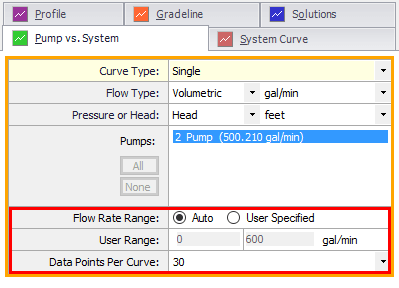
The way that AFT Fathom generates the system curve is that it will take the model into the background as it generates the system curve and it modifies the pump to a pseudo-fixed flow pump. Then the model is run over a range of flow rates. At each flow rate, the pump head that is required to overcome the system resistance and elevation change at that flow rate is calculated. After the model is run several times over a range of flow rates, it is the resulting pump head requirements at each given flow rate that will be plotted in order to generate the system curve. Figure 6 shows you exactly what range of flow rates the pump is run at to generate the system curve. The "Flow Rate Range" can either be automatically generated by AFT Fathom, or directly specified by the user. Then based upon the number of "Data Points Per Curve" (which is 30 by default), the user can determine exactly what flow rate values are used for the system curve generation process. The pump curve that is plotted is simply the user-defined pump curve.
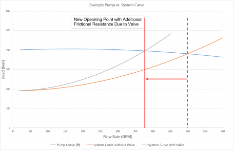
Now let's take a look to see what happens to the system curve when there is extra resistance in the system which can be modeled with a valve. In general, as frictional resistance in a system increases due to the addition of fittings or pipe corrosion, the system curve will typically become steeper. Therefore, the operation of the pump will operate further back on its curve to provide more head at lower flowrates due to the increased resistance. A manual throttling valve can change the overal system resistance as it is opened and closed. The reason why a manual throttling valve will change the shape of the system curve is because it is a "static component" as it will always remain in one single position, no matter what else is happening in the system, unless something forces the valve to change position. We have added a valve to the system shown in Figure 3 and we will assume it is stuck in a single position. As you can see in Figure 7, the system curve has gotten steeper which represents the additional frictional resistance from the valve and the operating point has decreased to a lower flow rate.
A control valve has a much different impact for a system because it is considered an "active component". This means that as various conditions change in the system, the control valve will constantly change in order to continually maintain its set point. Because the pressure drop across the control valve is always changing so the set point can be met, determining a unique system curve will be more complicated. When considering the system with a manual throttling valve, Figure 7 shows that a unique system curve can be developed because as the flow rate through the pump is changed in order to generate the system curve, the manual throttling valve will remain in the same position during that process. However, this is NOT the case for a control valve. As the flow rate through the control valve changes during the system curve generation process, the pressure loss across the control valve will change to continue meeting set point. As the set point is met, the pressure loss and flow rates are known and the Cv can be calculated. Therefore, with a changing flow rate and changing pressure loss, the control valve Cv value (i.e., open percentage) will be different over a range of changing flow rates! This can best be demonstrated with the usage of the AFT Fathom XTS module.
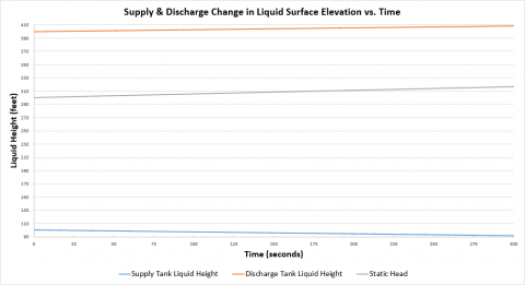
The model shown in Figure 8 is very similar to the system in Figure 3, but includes a Pressure Sustaining Control Valve which is set to control the upstream pressure to 210 psia (14.5 bar). The AFT Fathom XTS module has been activated so the model can use finite reservoir junctions to be more representative of tanks. During the transient, the liquid surface elevation for the supply tank will drain over time while the initially empty discharge tank will begin to fill up over time. As the pump operates continuously at 100% speed while the tanks are filling and draining, the control valve will constantly be changing its position over time to continually maintain set point because the Static Head in the system will be changing over time.
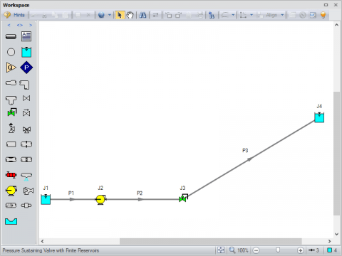
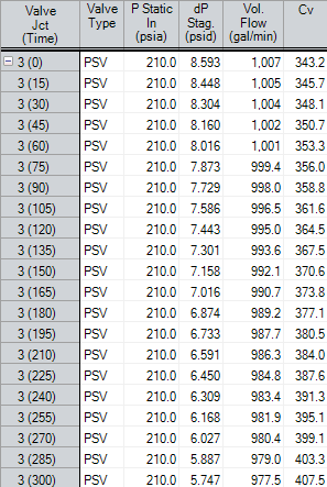
Figure 9 shows the resulting change in the supply and discharge tank liquid surface elevations over time as the pump continues to drain the fluid from the supply tank to filling up the discharge tank. Also plotted is the changing static head over time. Because the static head is changing over time, the control valve will constantly respond to this by changing it's Cv value (i.e., its open percentage) in order to always maintain a set point of 210 psia (14.5 bar). Figure 10 shows how the Pressure Sustaining Valve set point remains at a constant pressure while the pressure drop, volumetric flow rate, and Cv values are changing due to the change in static head over time.
This is why "active components" such as control valves lead to a non-unique system curve and it is because the control valve's own resistance is constantly changing at the same time as the system resistance changes when the system cuve generation is attempted over a series of flow rates.
There are two ways as shown in Figures 11 and 12 that dictate how you can generate a pump and system curve when there is a control valve in the system. The preferred way is to ignore the pressure loss across the control valve during the system curve generation process and this is represented in Figure 11. This will better represent the overall system resistance at a range of flow rates and the effect of the control valve is removed because it would change its own resistance over the range of flow rates. You can ignore the control valves in the system curve generation process by checking the boxes for control valves in the "Exclude Control Valves (Neglect Pressure Drop for These Control Valves)" section of the Pump vs. System curve generation tab.
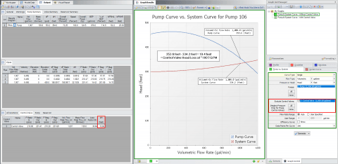
As you can see when neglecting the pressure loss across the control valve for the system curve generation, the pump and system curves will NOT intersect at the operating flow rate. However, the difference between the pump curve head and system curve head at the operating flow rate will be equal to the head loss across the control valve. That being said, this is not necessarily by design, the results will work out this way when there is only one control valve. If there are multiple control valves in parallel that have the same flow split, then the pump and system curve head differences will typically equal the average of the head loss through each control valve. However, if multiple control valves exist in parallel and they have different set points that lead to an unequal flow split, then the difference in head curves will not simply equal the average of the head loss across the control valves in that case.
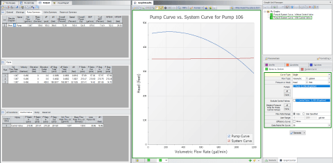
Figure 12 shows the pump vs. system curve for the case of including the control valve losses by unchecking the box for the control valves. Here, the pump and system curves will intersect at the operating flow rate. However, the system curve has a much different shape due to the additional frictional resistance from the control valve.
Overall, this should now provide you a much better understanding of what pump and system curves are and how they can be generated in AFT Fathom. It should also now be clear how the inclusion of manual throttling valves and control valves have an impact on a system curve. A manual throttling valve that is stuck in a single position will change the steepness of the system curve depending on how it is opened or closed and this will cause the operating point to move back and forth on the system curve. A control valve is a form of "active resistance" which means that the control valve resistance will constantly change in response to system conditions to continually maintain set point. This additional control feature complexity will have different impacts on the resulting system curve depending on whether or not the loss from the control valve is included in the system curve generation process.
Here is where you can read "Know Your Pump & System Curves - Part 2A" and "Know Your Pump & System Curves - Part 2B". In these two blog articles, I discuss system curve related aspects for systems with multiple branch points to several discharge reservoirs as well as for when multiple pumps exist in different locations of a system.


Comments 3
It would explain why flat curves are popular in HVAC
Such a great article this can really help a lot of people to decide what is the best for pressure equipment t
Amazing explanation.