AFT Blog
When Should You Use Variable Pipe Resistance?
Have you ever finished running an AFT Impulse model and then received the following Warning message shown in Figure 1 and then wondered what it means?
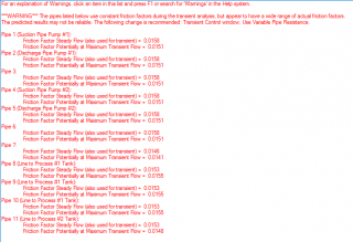
During a waterhammer analysis, the flowrates are constantly changing all throughout the system, therefore, the velocities and Reynold's numbers are also constantly changing. The friction factors will also be constantly changing during the transient. By default, AFT Impulse will use the friction factors that are obtained during the steady-state analysis and then use the same friction factors during the transient and they will be assumed to remain constant.
Since it is possible for the flowrates and Reynold's numbers to change quite signficantly during a transient, the friction factors may also change significantly and information about how much the friction factors might change is what follows the Warning message. For each pipe, the friction factor used during steady-state is displayed as well as the friction factor that can potentially occur at a maximum flow rate during the transient. The results in this case may not be reliable because the friction factors would be changing in reality when AFT Impulse assumes a constant friction factor.
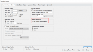
There is a way to account for the changing friction factors during the transient such that a new friction factor is calculated at each pipe station for every new time step during the simulation. This ability to allow the friction factors to change during the transient is enabled in the Transient Control window by checking the box for "Variable Pipe Resistance" as shown in Figure 2. The Variable Resistance option would allow a more accurate solution for the analysis.
So wouldn't you always keep the Variable Resistance option enabled so you can always ensure an accurate solution in order to avoid the big red warning messages? Well, not necessarily. It is important to consider the trade-offs. The biggest impact on run time is how the pipes are sectioned in the model and this is an excellent video tutorial that will provide very useful information on how to section pipes more effectively. The second most significant impact on run time is due to Variable Resistance. When the Variable Resistance option is enabled, the transient run time is typically increased by a factor of three! If it is possible that the Variable Resistance is going to make the run time potentially three times longer than if constant friction factors were used, how much accuracy will be sacrificed by not enabling Variable Resistance?
You can easily determine the impact to understand exactly how much the results will change by simply using the Scenario Manager to run the model WITH Variable Resistance set in one scenario and WITHOUT variable resistance in the other scenario.
Outside of run time reasons, when is it important to enable Variable Resistance? The answer is typically if you are modeling a pump startup scenario or if you have a flow path that is initially closed off. Essentially whenever you have a portion of the system that initially has no flow, and then can later allow flow during the transient. During the steady-state portion of the transient, in the areas where there is no flow, the Reynold's numbers will be very small, and the friction factors could be large. Then during the transient, these larger friction factors would continue to be used without enabling Variable Resistance. This is when you would consider allowing the friction factors to change.
Note that it is very important to pay attention to the Warning messages shown in Figure 1 and then locate where the pipes are in the model that show the differing friction factors. Many times, you may see these warning messages for pipes that are in flow paths that are either dead legs or are closed off to have no flow and remain off during the entire transient. If these are the pipes that the Warning messages are shown for, Variable Resistance may not be needed.
As I had mentioned previously, you can easily determine the exact impact on results when using or ignoring Variable Resistance. For the majority of cases (even for some pump startup cases), the effect of Variable Resistance is usually very small, if it even has an impact. Discussed below are two different cases that come directly from AFT Impulse's examples help file which shows how much enabling Variable Resistance impacts results. Spoiler alert...The answer is that for these two cases, there is virtually no impact at all on results by enabling Variable Resistance!
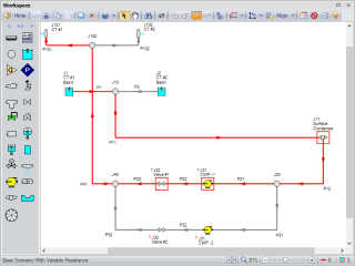
Figure 3 is the cooling tower piping system that is modeled in the "Pump Trip with Backflow" tutorial from AFT Impulse's example help file. The transients modeled are pump trips and valve closures. The pumps trip at the beginning of the simulation time and the valves start to close at the beginning of the simulation as well over a period of twelve seconds. The total simulation period is for 30 seconds. I have selected a continuous flow path in Figure 3 from the CT #1 Basin to CT #1 through pump CWP-1, as this will be a flow path that we can use to compare maximum and minimum transient results.
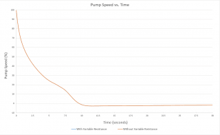
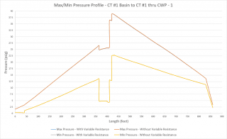
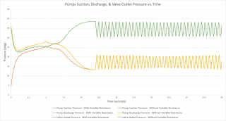
After running the model in two scenarios with Variable Resistance enabled and not enabled, I plotted the results together for the pump speed decay over time, maximum and minimum pressure profile for the flow path in Figure 3, and the transient pressures for the pump suction, discharge, and valve outlet. The graphs shown in Figures 4, 5, and 6 easily show how the results are identical for when Variable Resistance is enabled and not enabled.
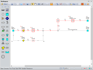
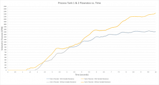
Now let's take a look at a pump startup scenario where Variable Resistance may need to be considered. Figure 7 shows a system with parallel pumps and discharge valves and both pumps and discharge valves will be starting and opening from the beginning of the simulation. As the pumps come up to speed, flow initally only gets delivered to the Process #2 tank. Once the pressure at branch J7 reaches 45 psig, the Valve to Process Tank #1 will begin opening to allow flow to Process #1 Tank. Note that in Figure 7, I have also selected a flow path that will be analyzed for the results.
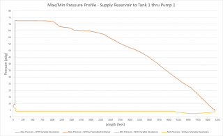
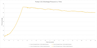
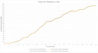
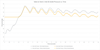
The results shown below in Figures 8 - 12 show that even for this particular pump startup scenario where there is initially no flow in the system, the results are virtually the same for accounting for Variable Resistance as without accounting for Variable Resistance.
Overall, Variable Resistance can be used in order to allow the friction factors in the pipes to change over time as the flow rates change which will produce a more accurate solution, but will cause the model to run about three times longer. As shown in both examples, you will often see that accounting for Variable Resistance may not cause any significant difference in results and thus, can be neglected to reduce run times. Even for pump startup cases, enabling Variable Resistance still may not cause that much of a difference in results either. Before simply making a decision to always use Variable Resistance, run your model in two scenarios where Variable Resistance is enabled and not enabled and you can easily quantify how different the results will be.


Comments