


AFT Blog
Welcome to the Applied Flow Technology Blog where you will find the latest news and training on how to use AFT Fathom, AFT Arrow, AFT Impulse, AFT xStream and other AFT software products.
4 minutes reading time
(747 words)
Not a Leak! Modeling Multi-stage Pumps with Discharge Flow Between Stages
AFT Fathom has long included the ability to model multi-stage pumps by representing them with an overall effective pump curve. New in AFT Fathom 10 is the ability to model "Interstage Bleed" or "Takeoff Flow" in these multi-stage pumps.
It is well known that arranging pumps in series has the effect of increasing the available head at a given flow. Large multi-stage pumps can be thought of as a series of smaller pumps - the impellers - all working together to increase the overall available head. Each impeller - stage - increases the pressure of the working fluid some incremental amount. This equivalency is demonstrated in the below AFT Fathom 10 model. Keep in mind that the connector pipes between stages are frictionless.
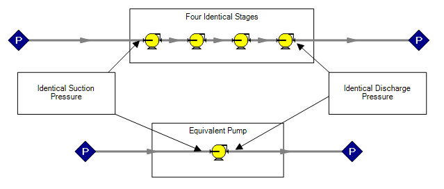
Figure 1 - Equivalent Representations of a Multistage Pump
What happens if we extract some flow at some interstage point? In some applications, particularly in the power industry, it is more efficient to "tap in" between stages of an existing pump and extract flow at the intermediate pressure. This alleviates the need to install an entirely new pump for a relatively small secondary process.
We are adding a branching flow to our model in between the stages. Again, note that there are no pipes between stages in reality - the extraction takes place directly from the pump casing.
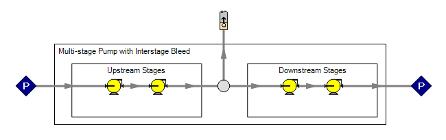
Figure 2 - Interstage Flow
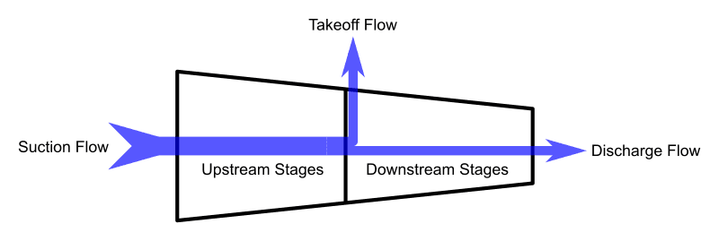
Figure 3 - Simplified Interstage Pump Schematic
AFT Fathom has no issues solving this model - the appropriate flows and pressures will be found for all of the stages and piping connections. Unfortunately, this model assumes that the user knows the Pump Curves for each individual stage in the pump - information that is very unlikely to be readily available.
Instead, a manufacturer of such a pump is likely to provide only two curves:
- Overall Pump Curve - the head developed across the entire pump when the Takeoff Flow is zero.
- Upstream Stages Pump Curve - the head developed across all of the stages upstream of the Takeoff point.
Note that the Upstream Stages Pump Curve is not directly affected by the amount of Takeoff Flow - it can be thought of as an entirely independent pump. In order to model the Interstage Pump as two separate pumps, we need to know the Downstream Stages Pump Curve.
We can calculate this curve by subtracting the Upstream Stages Pump Curve from the Overall Pump Curve. The Upstream Stages and Downstream Stages Pump Curves are constant curves for a fixed speed. Neither curve changes with a varying Takeoff Flow.
However, if there is a non-zero Takeoff Flow, each curve will be operating at a different flow. The Upstream Stages Pump Curve will contribute head according to the point on the curve at the Suction Flow amount. The Downstream Stages Pump Curve will contribute head according to the Discharge Flow. The total head contributed from Suction to Discharge is the sum of these two values.
There is one more Pump Curve that we can define for the device - an Overall Effective Pump Curve. This curve relates the actual head generated from Suction to Discharge at a given Discharge Flow. The actual head generated at any given Discharge Flow will be less than that indicated by the Overall Pump Curve if there is any Takeoff Flow. Some energy is being lost to the intermediate bleed.
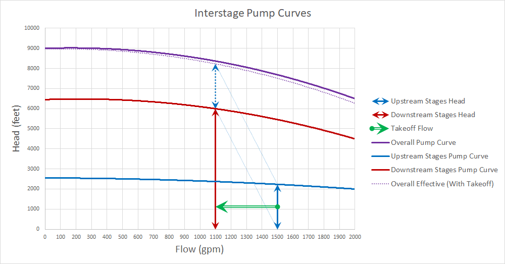
Figure 4 - Pump Curves and Takeoff Flow
How can we represent this in AFT Fathom 10? Thankfully, it is easy with the new Interstage Bleed feature.
Two Pump Junctions can be linked to one another, allowing AFT Fathom to determine the Downstream Stages Pump Curve, and only requiring manufacturer data from the user.
First, lay out your model with two Pump Junctions. The pumps must be connected with Pipes - by default, Pipes in AFT Fathom have pressure losses associated with them. Because there are not truly "pipes" connecting the two halves of the pump, these pipes should be very short in length, or preferably modeled as frictionless.
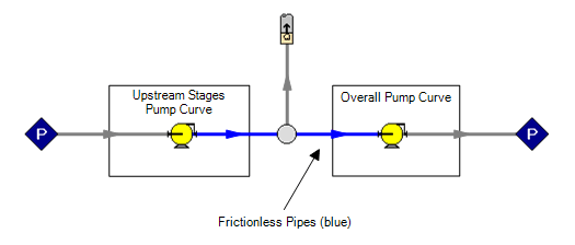
Figure 5 - Interstage Pump in AFT Fathom
To tell AFT Fathom that these two pumps are in fact connected, check the "Interstage Bleed/Takeoff Flow" option in one of the two Pump property windows and select the Pump that it is linked to.
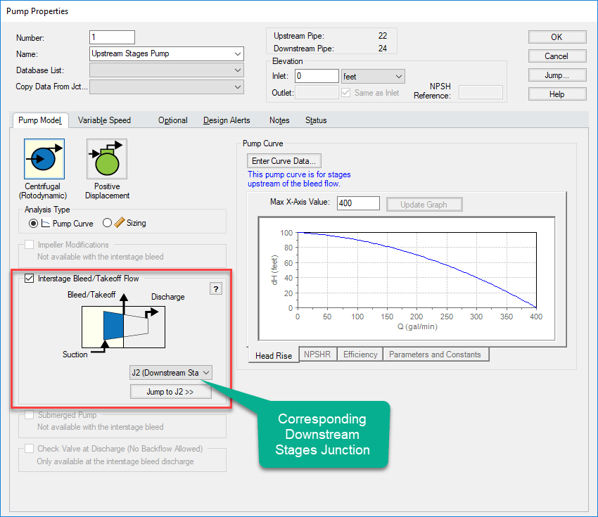
Figure 6 - Defining the Pump
The corresponding Pump is automatically updated.
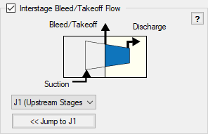
Figure 7 - Connected Pump
That's it! The system is now defined and can be solved. Any configuration of pipes can be connected to the Suction, Discharge, or Takeoff points of the Interstage Pump. AFT Fathom's powerful network solver will account for the pressure losses throughout the system to determine what the actual flows and pressure are.
Comments 2
Dear Scott,
If we have not the AFT Fathom 10 version, we can construct the overall pump curve (with take off), by using interstage pump curves, bearing in mind all stages are identical and have identical curves, so after constructing the overall system curve outside the software we can feed the new system curve as a new pump, the one is depicted with dashed lines, do you agree with this?
Kind Regards
Michael Shahrokhani
Hello Michael,
Thank you for your question!
This feature in AFT Fathom 10 is primarily a convenient way to calculate the pump curve for the downstream stages (after the takeoff flow point). If the pump curves for each individual stage (or group of stages) is known beforehand, then those could be entered directly into normal pump junctions giving the same effect. Generally, these curves are not readily available so the feature was added to calculate them.
I am not sure what you mean when you say "construction the overall system curve outside the software." A system curve cannot be input directly into AFT Fathom 10. Only pump curves can be defined as the system curve is a property of the system (components, pipes, etc).
If you have the dashed line "Overall Effective (With Takeoff)" pump curve, you could enter this as the pump curve for a single pump junction. This assumes that the takeoff flow has no impact elsewhere in the system (it is entering the environment or a separate system) and it assumes that the takeoff flow remains constant (the effective curve will change for different takeoff flows).
If the takeoff flow depends on the system operation, the shape of the overall effective curve will be linked to the system operation, which is in turn linked to the pump behavior. This means that iteration would be required to determine the effective curve. However, it could certainly be done by hand.
Let me know if this addresses your question!