AFT Blog
Iso love the new Pipe Drawing Mode!
Have you ever wanted to show the three-dimensional nature of your piping system in AFT applications? Maybe you are building a model from an isometric reference drawing. Or maybe you are incorporating your model into a report and want to represent the x, y, AND z axes.
Whatever the reason may be, the great news is that AFT Fathom 10 includes a new Isometric Pipe Drawing Mode!
There are three Pipe Drawing Modes available on the Arrange menu: 2D Freeform, 2D Orthogonal, and Isometric.

Figure 1: Pipe Drawing Modes available on the Arrange menu
Figure 1 shows the differences between the three Pipe Drawing Modes. The 2D Freeform mode will place a pipe on the Workspace as drawn. The 2D Orthogonal mode will segment the pipe onto the orthogonal grid. The Isometric mode will segment the pipe onto the isometric grid.
To show the grid as in Figure 1, go to the Arrange menu and select Show Grid. The remainder of this blog will focus on how to best utilize the Isometric Pipe Drawing Mode.
Isometric Pipe Drawing Mode
When you draw a pipe, a red-dashed preview line will display. The preview line shows where the pipe will be drawn. To view other options for the pipe, you can scroll the wheel on your mouse or click any of the arrow keys on your keyboard. When this is done, the preview line will change to show the alternate paths for the pipe. Once the preview line appears how you would like your pipe drawn, you can drop the pipe endpoint.
When you adjust a pipe by dragging the endpoint to a new position on the grid, only the opposite endpoint will stay fixed. However, if you hold down the Alt key while adjusting a pipe by the endpoint, the center vertex of the pipe will also stay fixed and an additional segment will be added.
The scroll wheel/arrow key function can be used in combination with the Alt key function to optimize drawing and adjusting pipes on the isometric grid. In all three Pipe Drawing Modes, you can Add/Remove Segments by right-clicking on a pipe.
The other unique aspect of using the Isometric Pipe Drawing Mode is that the visual appearance of the junction icons is more complex than in a 2D grid. Due to the increased number of axes, the preferred icon and rotation must be selected to obtain visual consistency. To change an icon, right-click on the junction and select Customize Icon, as shown in Figure 2.
![]()
Figure 2: Right-click on a junction and select
Customize Icon to choose the preferred icon and rotation
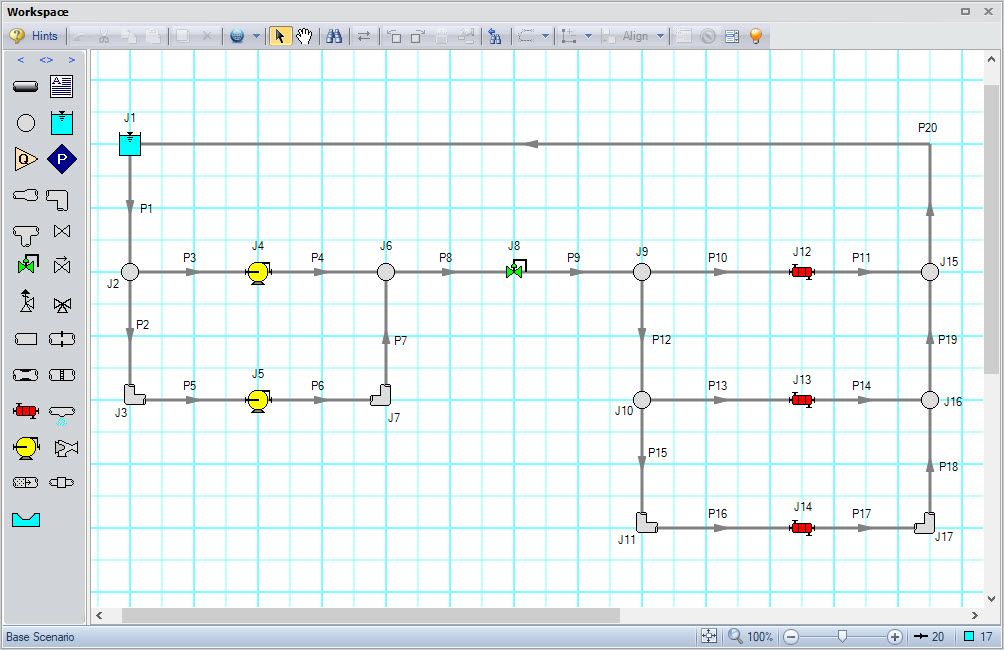
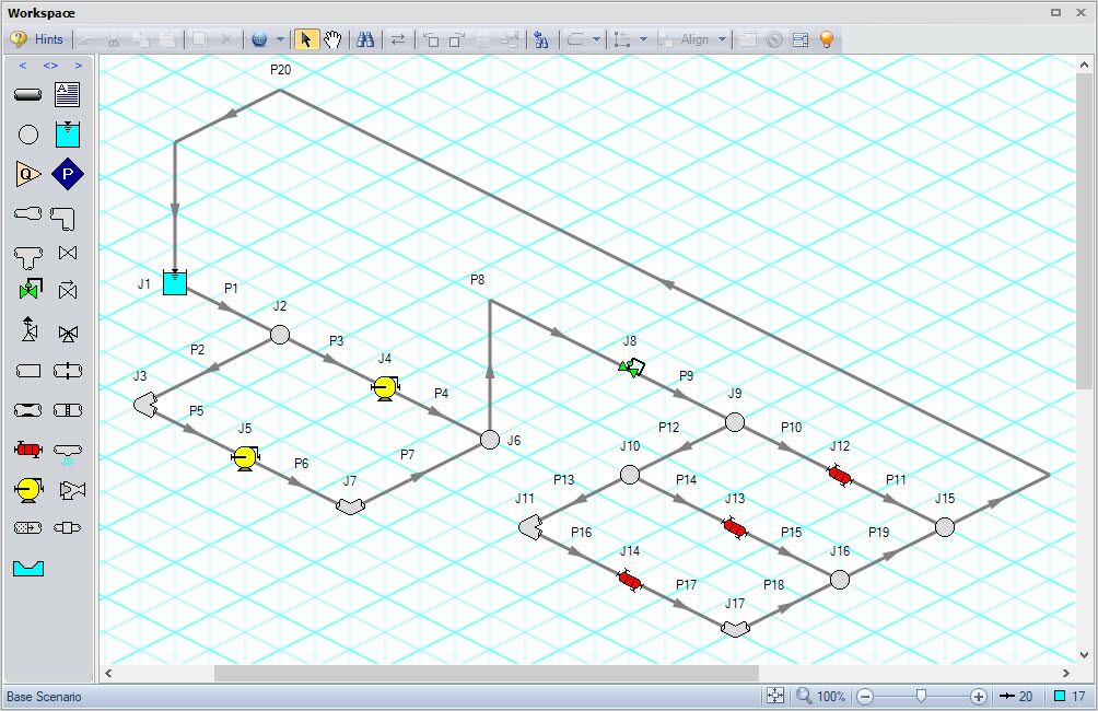
It’s as simple as that! With this knowledge about the Isometric Pipe Drawing Mode, it is quick and easy to take a 2D model (Figure 3) and represent its 3D nature on the isometric grid (Figure 4).

Figure 3: Cooling system drawn on a 2D grid

Figure 4: Cooling system drawn on an isometric grid
The Isometric Pipe Drawing Mode is available in AFT Fathom 10 and is coming soon in AFT Arrow 7 and AFT Impulse 7!


Comments