AFT Blog
Calculate Pressure Drop Across Sharp-Edged Perforated Plates
Sometimes design engineers will install a screen to protect equipment like centrifugal pumps. Screens are available in a variety of configurations, each with its own head loss characteristics. AFT Fathom provides a screen junction that allows users to choose from four different screen types:
- Perforated Plate (Sharp-Edged)
- Perforated Plate (Round-Edged)
- Circular Wire
- Silk Thread Screen
This article primarily discusses thin-walled, sharp-edged perforated plates with uniform diameter holes.
Every screen has an open flow area that allows the working fluid to bypass the screen while restricting any foreign objects that are not able to pass through this area. The open flow area is typically comprised of several apertures that are evenly distributed across the fitting. Industry sometimes refers to the flow area as porosity. To determine the flow area percentage of the screen, it is broken up into discrete segments, usually on a center point basis between openings. These segments are then dimensioned along with the open areas. The open area ratio (f), or porosity, can be calculated by dividing the open area of the segment by the total area of the segment.

There are several common geometries for perforated plates. These plates may have elongated geometries or simple round holes. The principle outlined above works with all types to determine an open area ratio. While the calculations may be easy enough to compute by hand, three circular configurations have been outlined below to save time. There are several tools available online to help calculate the open flow area ratio for various geometries, but users should manually verify the calculations presented on these websites. Several websites found during research for this article used incorrect formulas, so users should be wary.
Perhaps the three most common layouts are as follows; the square arrangement, a staggered profile, and a staggered profile where openings are offset by 60 degrees. Note that while the staggered profile will work for the 60-degree offset as well, it may be faster however to use the simplified equation. The three common layouts are shown below:
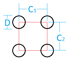

Figure 1 Square arrangement
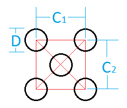

Figure 2 Generic staggered arrangement
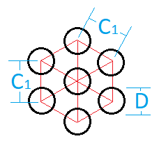

Figure 3 60-degree offset staggered arrangement
The calculated open area ratio can be used in the following equation to determine the plate’s loss K factor. This equation comes from Idelchik’s Handbook for Hydraulic Resistances, 1994 on page 516. The calculated K factor is then converted into a pressure drop normally in AFT Fathom’s solver.


AFT Fathom applies these equations to determine the pressure drop across the Screen junction when the “Perforated Plate (Sharp-Edged)” option is selected. By default, the upstream pipe area defines the ‘total area of segment’ which can be can be modified by changing the ‘Basis Area for Loss Model’ settings as found on the Screen Properties window in Figure 4.
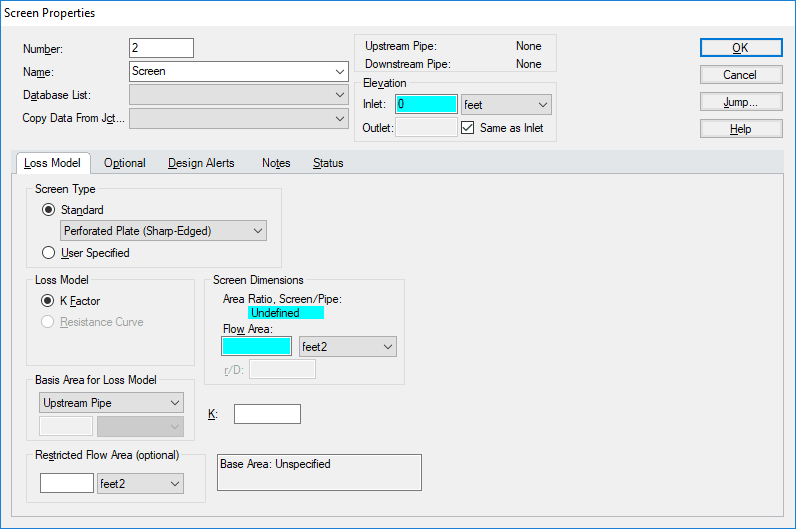
Figure 4 Screen Properties window
Users must specify the “Flow Area” of the orifice manually to calculate its pressure losses. Users will typically have access to the configuration information such as the staggering, spacing, and diameter of the holes on their perforated plates to determine their open area ratio. From this open area ratio, users can calculate a flow area for input into AFT Fathom.

An Example
Consider a perforated plate with sharp edges like the one shown in Figure 5. The holes resemble a square layout and are spaced every 0.5125 inches with a bore diameter of 3/8 inches. The screen is to fitted to a nominal five-inch steel pipe (hydraulic diameter: 5.047 inches). What is this screen’s K factor?
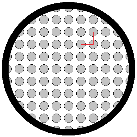
Figure 5 Example screen
To begin, one would determine the open area ratio of this screen using the corresponding porosity equation. Substituting the measured values into the equation as shown below, the open area ratio is 0.42045. Multiplying the open area ratio by the pipe area, the resulting flow area is 8.41 square inches. The flow area is then input into the Screen Properties window.
Users should verify the calculation by comparing the resulting open area ratio with that reported by AFT Fathom. Figure 6 shows the Screen Properties window with the above information entered. The K factor in this case is 7.56.


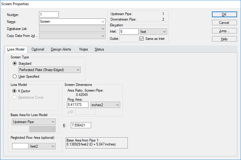
Figure 6 Screen Properties window filled out
It is easy to accurately predict the pressure drop across a perforated plate with sharp edged orifices as shown above. However, be mindful that the characteristics discussed above pertain to thin-walled plates. As plates become thicker, the frictional dissipation across the openings begins to resemble a tube bundle and as such the equations used to characterize this loss should change as well. There are other equations for both round edges and different methods to determine the open area ratio for irregular shapes and staggering patterns.
(This blog was originally written by Jake Miller and was updated by Nick Vastine in December 2022.)


Comments 1
This article is very good! I got much things from your articles.
I think it is much better if you can add a tool in AFT Fathom that we can select screen arrangement style(square or staggered) and specify the D, C1 and C2, then we get the loss factor K automatically.