AFT Blog
Is the Pipe Half Full or Half Empty?
Well that depends on how optimistic you are, but either way you can model partially full pipes with AFT Impulse! This means partially full along the axial direction, as opposed to partially full along the radial direction. This function only works for pipes that have a slope, and when the pipe is partially full it drains from the end with the higher elevation. Pipes which contain vacuum breaker valves, exit valves, spray discharges, or assigned pressures at the outlet can drain or fill during the transient. This draining or filling is limited to the specified pipe. AFT Impulse will not model an entire system draining. This feature is very useful in determining fill and drain times for fire water systems and high elevation pipelines.
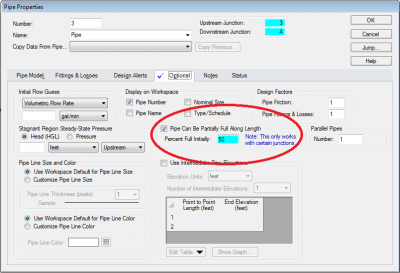
You turn on this option in the optional tab of the pipe properties window. You can select how full you want the pipe to be full initially. For the example 50 percent was selected.
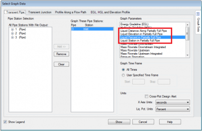
After clicking the checkbox for partially full pipes more options for output and graphing will appear.
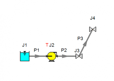
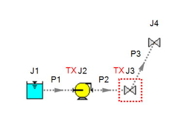
This simple model shows how the pipe’s liquid percent reacts when a pumps trips.
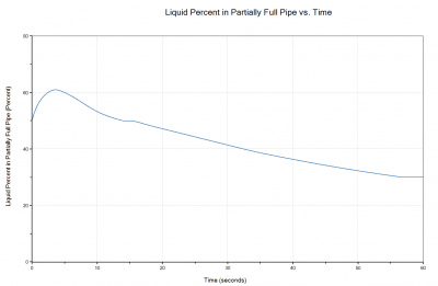
After running the model the Liquid Percent in Partially Full Pipe was graphed. This option is selected in the pipe transient tab in the select graph data window. The partially full pipe options for graphing are not station specific and selecting any of the station will yield the same output.
In the graph it can be seen that after the pump trips there is still enough inertia to continue filling the pipe for a short time, but then the pipe begins to drain and settle at a liquid level around 30 percent after 60 seconds.
A pump startup scenario was also modeled, but with valve J3 initially closed until the pump reaches a 20 percent of its speed.
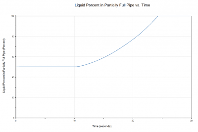
The below graph shows how long it take the pipe to fill to 100% after the pump starts up.
Here you can see that it takes 10 seconds for the pump to reach 20 percent of its speed and after the valve opens it takes around 15 second for the pipe to fill up 100%.
Here you can see that it takes 10 seconds for the pump to reach 20 percent of its speed and after the valve opens it takes around 15 second for the pipe to fill up 100%.
This feature is useful for determining if too much air is entering your model and showing how the system responds to the introduction of air into your relief system. Start integrating this into your system for more accurate modeling of fire suppression, vacuum breaker valves, and other forms of pressure relief.


Comments