AFT Blog
Calculating Flow Through an Orifice Using ASME MFC-3M-1989 and Irrecoverable Pressure Drop Equations
Recently, a customer calculated the mass flow rate of a fluid through an orifice using both the ASME standard MFC-3M-1989 and AFT Arrow. He was puzzled when this mass flow rate calculation differed by approximately 100 lbm/hr between the two methods, so he reached out to AFT for help in determining the reason for the discrepancy. The answer for the difference in flow rates on a basic level is that these two calculations are, fundamentally, not the same thing; ASME correlates differential pressure at pressure taps for purposes of flow measurement, while AFT Fathom and Arrow calculate the irrecoverable pressure drop across the orifice for purposes of system pressure loss.
ASME MFC-3M-1989 ORIFICE FLOWMETER
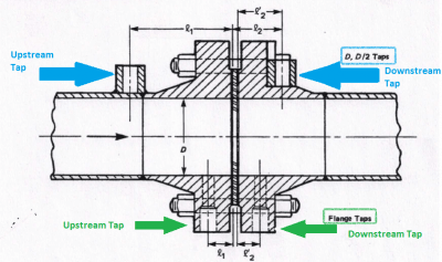
The ASME standard utilizes the differential pressure measured across pressure taps located very near the orifice in areas specified by the standard. In this region, the static pressure changes due to irrecoverable pressure losses from increased friction and turbulence in the flow, as well as pressure changes that are a result of the vena contracta and complex flow patterns as the fluid progresses through the orifice. It is crucial to note that this measured pressure differential is not equal to the irrecoverable pressure drop. The pressure profile particular to flow through a given orifice and its immediate upstream and downstream piping will vary based on several factors that, aside from computational fluid dynamics (CFD) modeling, can only be determined with experimental data. The ASME standard, then, is applicable only to systems that follow the pressure tap and orifice type, placement, and installation guidelines established by the standard. Figure 1 from the ASME standard (Reference 1) shows the configuration of an orifice with both D and D/2 taps and flange taps.
The ASME standard provides Equation 1 to calculate mass flow of a liquid through an ASME orifice flowmeter when the orifice flowmeter diameter is at the temperature of the flowing liquid:

Where:
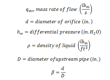
EQUATION 1: Flow through ASME Orifice Flowmeter (Reference 1, page 10)
For D and D/2 taps, the equation for C (the discharge coefficient) to be used in Equation 1 is:

![]()
EQUATION 2: Discharge Coefficient for D and D/2 Pressure Taps (Reference 1, page 30)
To convert from hw to a true pressure drop, the following relationship between head and pressure is used:
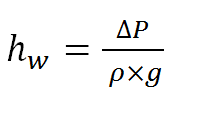
IRRECOVERABLE PRESSURE DROP EQUATIONS FOR ORIFICE FLOW
AFT software calculates the irrecoverable pressure drop across an orifice using several methods. Perhaps the most popular method uses a K factor (Equations 3 and 4). The K factor is calculated using correlations from various hydraulic resistance sources. In the following example, the K factor was calculated to be 52.6 from I.E. Idelchik’s Handbook of Hydraulic Resistance (Reference 2, page 221). Crane Technical Paper 410 (Reference 3, page 4-5) was also used, and a K factor of 56.0 was calculated using this reference. After the K factor is calculated, it is used in the following equation to calculate head loss:
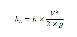
Where
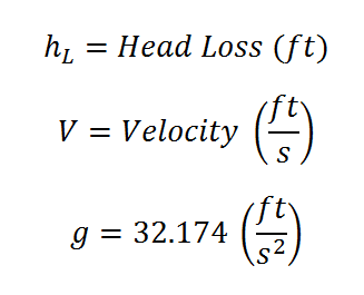
EQUATION 3: Irrecoverable Pressure Drop in terms of Head Loss (Reference 3, page 2-7)
Converting head in Equation 3 into pressure using the following equation gives Equation 4.
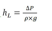
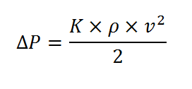
EQUATION 4: Irrecoverable Pressure Drop in terms of Pressure
SAMPLE CALCULATIONS
To demonstrate the appropriate use of both of these calculation methods, an example calculation was created. The flow was specified at 100 gpm with a 1 inch orifice diameter and a 2.25 inch upstream pipe diameter. The differential pressure across pressure taps was calculated using the equation given in the ASME standard, and the irrecoverable pressure drop across the orifice was calculated using spreadsheet calculations. These calculations were confirmed in AFT Fathom. This principle applies to gas and steam flow, but an incompressible fluid (water at 50°F) was used here for simplicity as varying densities complicate these calculations.
*Note: the ASME standard provides correlations for three types of pressure taps (flange, D and D/2, and corner taps), but the difference in calculated differential pressure was within 0.2 psid for all three pressure tap types, so the correlation for D and D/2 taps was used.
The results of this analysis are shown below:

FIGURE 2: ASME Orifice Flowmeter Pressure Differential for 100 gpm Water Flow
(from Equation 1)

FIGURE 3: Irrecoverable Pressure Drop Across an Orifice with 100 gpm Water Flow
(from Equation 4)
As can be seen from the results shown in Figures 2 and 3, the pressure differential measured at the flowmeter pressure taps is different than the irrecoverable pressure drop.
The ASME standard does provide a correlation to relate the differential pressure at the orifice flowmeter to the irrecoverable pressure loss of the orifice flowmeter. This equation is shown in Equation 5.
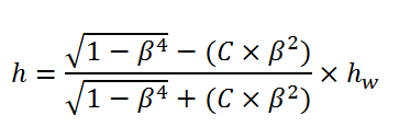
EQUATION 5: Irrecoverable Pressure Drop Across an ASME Orifice Flowmeter
(Reference 1, page 32)

FIGURE 4: Irrecoverable Pressure Drop Across an Orifice using ASME Equation 5
This irrecoverable pressure drop predicted by the ASME standard for the orifice flowmeter (Figure 4) is very close to that calculated in Figure 3. This further illustrates that the ASME flowmeter differential pressure (Figure 2) is not the same thing as the irrecoverable pressure drop across an orifice (Figures 3 and 4). AFT software uses Equation 4 to calculate the irrecoverable pressure drop across an orifice.
CONCLUSION
When it comes to assessing flow rate through an orifice, ASME standard MFC-3M 1989 relates a pressure differential across pressure taps while AFT software calculates an irrecoverable pressure drop associated with the orifice. Therefore, while both of these methods ultimately calculate flow through an orifice, the equations associated with each were developed to be applied differently, and the user must be cautious to ensure that his/her input is applicable to the particular calculation method used.
REFERENCES
- ASME MFC-3M-1989. “Measurement of Fluid Flow in Pipes Using Orifice, Nozzle, and Venturi”. Date of Issuance: January 31, 1990.
- Idelchik, I.E. Handbook of Hydraulic Resistance. 3rd edition.
- Crane Co. “Flow of Fluids through Valves, Fittings, and Pipe Technical Paper No. 410”. Reprinted 11/09.


Comments 4
So you are looking at a ~10 to 12% difference between a typical flow orifice calc. and arrow. Is there some factor on arrow that you can correct to get it closer to matching the typical orifice calculation.
Hi Eric and thank you for the question.
The main point here is that the dP you are measuring across the orifice IS NOT equal to the total, irrecoverable pressure loss. Therefore, there is no factor that can be applied to Arrow, because the dP you have measured is not relevant to a necessary input in Arrow.
To expand on this idea, think about the upstream and downstream pressures you measure in the field in accordance with the standard. This pressure is very near the orifice where there is a vena contracta and other physical phenomena occurring. If you measure a static pressure of 200 psia at this point and input this as the upstream pressure in Arrow, you are telling Arrow that the static pressure is 200 psia, but Arrow is associating this static pressure with the pipe diameter you have modeled, not the actual flow diameter (due to the vena contracta). This means that Arrow calculates a different velocity at this point than actually exists in your system, which, according to the fundamental equations, results in a different overall irrecoverable pressure drop.
Fortunately, you can easily correlate the pressure loss measured across the orifice according to the standard, to the standard's equation for overall irrecoverable pressure loss (this is Equation 5 in Figure 4 in the article).
This overall, irrecoverable pressure loss is what Arrow needs to accurately represent your system. Once you have calculated this overall irrecoverable pressure loss, you can model the orifice in Arrow to take this pressure drop, and a factor to get Arrow to match up with your field results will be unnecessary because Arrow will now match the hydraulics of your system (assuming your system is modeled accurately otherwise).
I hope this clears up your question, but please let me know if you have any follow-up questions. You can always call or email our support system, as well. Thanks Eric!
Erin What standard(s) should I use to measure the uncertainty if i want to measure the flow with an orifice plate 2" in a 4" pipe line.
Hi Jesus,
Thank you for your comment.
A definitive answer to your question is outside the scope of this blog and the advice I can provide as AFT software is used in a vast range of industries that all may have different procedures/standards to determine the uncertainty in flow rate measurement. However, the more recent version of the standard referenced in this blog, ASME MFC-3M-2004, does provide some calculations for measuring the uncertainty of flow rate measurement on pages 9 and 10, including referring users to ASME MFC-2M and ISO/TR 5168 for more detailed information. There is a section entitled "Practical Computation of the Uncertainty" that will hopefully prove helpful to you.
Additionally, once you have determined the uncertainty, it is a good idea to model the system with the upper and lower possible flow rate values to observe how your system pressures and flows (elsewhere in the system, depending on how your system is configured) will be affected with these different flows. You may find that, even with the uncertainty in flow rate, the system requirements are still met. You may also find that more analysis and/or system modifications need to be done to ensure that your system will function as desired.
I hope this clears up your question, but please let me know if you have any follow-up questions. You can always call or email our support system, as well. Thanks Jesus!