AFT Blog
Use Control Valve Junctions to Size Valves and Orifice Plates
AFT Fathom can EASILY size valves AND orifice plates with a SINGLE Control Valve junction! There is no need to perform strenuous hand calculations to determine a valve Cv or an orifice diameter. Just specify the system boundary conditions, pipe input properties, and the desired flow rate (or pressure) and AFT Fathom will calculate the Cv, K factor, and equivalent orifice diameter/area for you all at once!
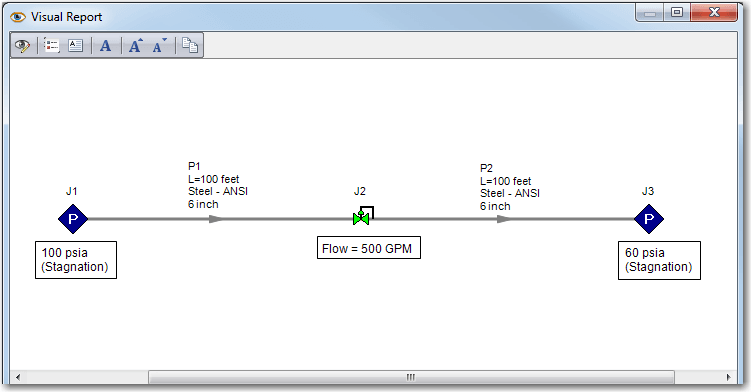
Figure 1 illustrates a control valve junction at the location of a valve or an orifice plate. For known flow, use a Flow Control Valve (FCV). For known upstream pressure, use a Pressure Sustaining Valve (PSV). Or use a Pressure Reducing Valve (PRV) for a known downstream pressure.

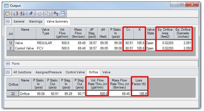
After specifying the input and running the model, the Cv, K factor, and equivalent orifice size (based upon a discharge coefficient of 0.6) will be displayed in the Valve Summary tab of the Output window. The results based on a known flow rate of 500 GPM are shown in Figure 2.

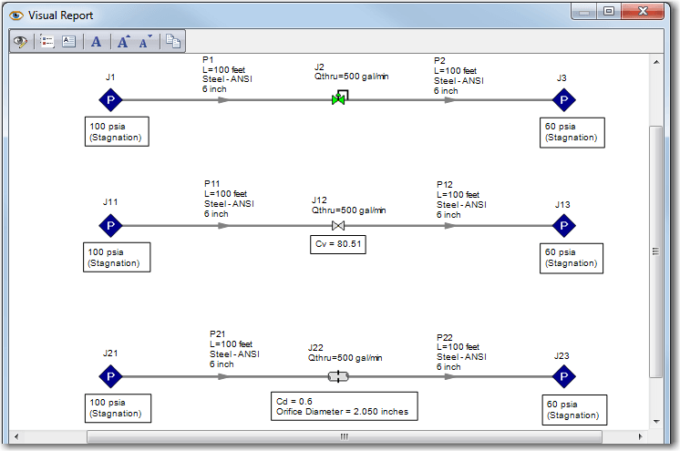
Finally, to verify AFT Fathom’s ability to size a valve or an orifice plate with a Control Valve junction, build identical systems on the same Workspace using the Duplicate Special feature (click here to read the Duplicate Special feature Tips and Tricks blog post). Then, morph the duplicated Control Valves into a valve and orifice plate by holding the Control key down and dragging a valve and an orifice junction directly on top of the existing Control Valve junctions. Figure 3 shows the result of the original Control Valve system that was duplicated twice with Duplicate Special, and then the duplicated Control Valves were morphed to a regular valve and orifice junction.
Figure 3: Select the top system with FCV J2 & Duplicate Special twice. Then morph the FCV in the middle system to a valve and the bottom system to an orifice.
Once the resulting Cv or K factor is specified for the valve, and the equivalent orifice diameter with a discharge coefficient of 0.6 is specified for the orifice, the final results in Figure 4 show that the valve and orifice plate were sized correctly. Notice how the resulting flow rates, valve Cv’s, K factors, and orifice sizes are the same!


Comments 5
To control flow, Can we place control valve before orifice plate ?
Well, you could place a control valve upstream of the orifice plate to control the flow. However, the idea behind this article is how you would use a control valve junction to size an orifice plate as described in the article. Note that if you were to place a control valve upstream of an orifice, A) You should only do this if that is how your system is actually set up and B) Pressure drop will then occur at two places, the control valve AND the orifice. Therefore, if you do NOT have a control valve in the real system, then this would essentially be taking out more pressure loss in the model than is represented in your system. Hope this helps clarify and thank you for your question!
Hi I can not find the equal orifice plate in fathom 10?
Hi Ben - this is a good tutorial, but I am not able to get the equivalent orifice diameter or area in the output window in AFT Fathom 9. What additional settings should I change to produce this data?
Hi Adam, thanks for your question! What you need to do is to open the Output Control window, then click on the "Valves" button in the Display Parameters tab. That is where you can find the "Equivalent Orifice Area" and "Equivalent Orifice Diameter" parameters in order to add them to your Valve Summary in the General Section of the Output window.