AFT Blog
Efficient Modeling Using Pipe Property Features
Complex piping networks can often be simplified using two powerful features available in AFT Fathom 8 and AFT Impulse 5. Under the “Pipe Properties” window, the “Fittings and Losses” tab and the “Use Intermediate Elevations” feature on the “Optional” tab allow the user to specify several fittings and elevation changes that otherwise would be input as separate pipes and junctions. These features allow the user to save workspace and maintain a very accurate representation of hydraulic losses through their systems.
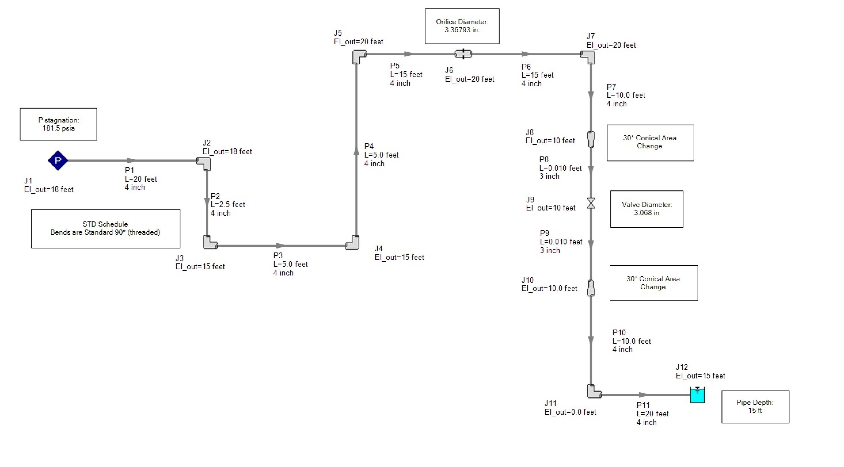
As an example, Figure 1 below shows a simple pipe network using ANSI Steel pipe, AFT Standard water at 1 atm and 70 °F that discharges into the bottom of a tank with a 15 foot liquid surface elevation open to the atmosphere.
Figure 1: System schematic.
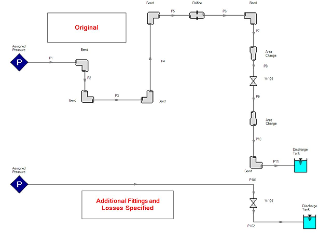
More complex piping systems could take more time to build and would use more Workspace area to fully represent the system. Using the features previously mentioned, this system could be simplified into one or two pipes. For the sake of available pressure outputs, the valve V-101 has been preserved and the system has been simplified from eleven pipes to two as seen in Figure 2 below.
Figure 2: Comparison of simplified version to original version.
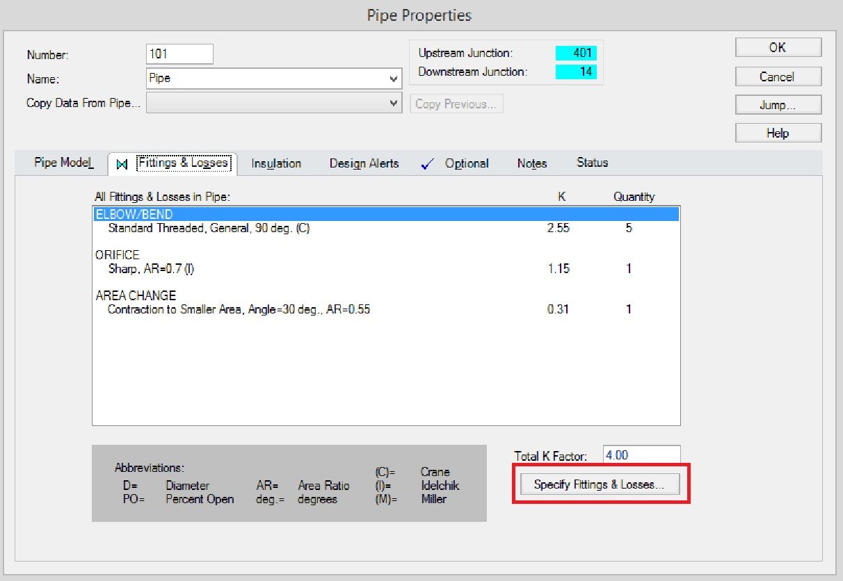
The user may input any losses or fittings listed after clicking "Specify Fittings & Losses...". One of the fittings covered in this examples is bends. Figure 3 below shows how the number of bends in the resulting pipe has been entered, in this case there were five. In Figure 3 you can also see the type of fittings covered in this menu near the top of the "Pipe Fittings & Losses" window.
Figure 3: Specifying Fittings and Losses.
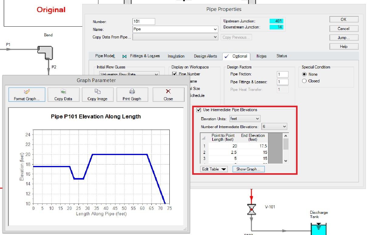
The inputs necessary for Pipe 101 to simplify everything before valve V-101 is shown below in Figure 4 and Figure 5. Similar losses were also input into Pipe 102. These inputs were appropriately selected from a variety of available losses!
Figure 4: Fittings and Losses for Pipe 101. Compare these to the original system.
Figure 5: Intermediate elevations for Pipe 101 and where they are found.
Differences between the simplified system and the original can be seen here in Figure 6. The plot of Pressure VS Length shows that the inlet and outlet pressures clearly agree. There is however a loss in resolution of pressure change that is present between and across each junction in the original. For certain systems these differences may be significant to the user in which case, these features may not be appropriate to that particular model. However, if the resolution in these areas is not of a high concern, then these features provide an efficient way to maintain the overall integrity of the system’s properties and cut down on model size or even build time in some cases!
Figure 6: Pressure VS Length. Red is the simplified model.
If using AFT Impulse 5, there is a “Combine Pipes” feature that is available in the “Section Pipes” window and it will not only combine pipe lengths of similar diameter and schedule type, but it will convert physical junction losses to additional pipe fitting losses and will do the same for junction elevations and intermediate elevations. This could also help lower model run times! Next time you’re modeling, be on the lookout for any pipes and junctions you may be able to simplify into fewer pipes by making appropriate use of these powerful features!


Comments