AFT Blog
Overcoming New Heights - System Priming Before Siphon Effect Can Help
The process of sizing a pump for the application of priming a piping system as well as for normal operation is slightly more involved than if the system was already primed and the pump was to be sized for a liquid full system. For a system priming application, the intermediate elevations at high points in a piping system are relevant in regard to the pump that is used. If a pump is not able to generate enough head in order to overcome the high intermediate elevation points in a system, then the pump will provide no benefit to the system, even if it was sized properly for a liquid full system.
Sizing a pump using AFT Fathom is incredibly easy! An important assumption to keep in mind though is that in AFT Fathom, all pipes are assumed to be liquid full. To size a pump for a system that is already liquid full, all you need to do is model a pump with a fixed flow rate and then let AFT Fathom determine how much pump head is needed in order to overcome elevation changes and system resistance. After that, you've got your flow rate and head rise operating point that you need to find a pump curve that will match.
There are situations that arise in which pump sizing is not as straight-forward as just determining the required head-rise. Consider the situation below as shown in Figure 1 where there is an intermediate elevation that is greater than the liquid surface elevation of the discharge reservoir. The design flow of the system is 1,000 GPM and the system static head is 10 feet. However, downstream of the pump, there is a 50 foot elevation change to a riser before the fluid flows into the discharge reservoir. As seen in the results for the AFT Fathom model of this system in Figure 2, when the system is liquid full, the pump has to generate about 25.5 feet of head to deliver 1,000 GPM through this system (Note that in AFT Fathom, the negative dH at the pump indicates the head rise across the pump). The reason why the pump only needs to generate 25 feet of head, even with a 50 foot elevation change downstream of the pump is because the siphon effect helps reduce the required head rise when the system is liquid full. The siphon effect helps because there is hydrostatic pressure recovery as the liquid in the pipe drops in elevation and the pressure increases. This is a key concept for why there is a difference in sizing a pump for a system that is liquid full in comparison to a system that has not been primed which has high intermediate elevation points.
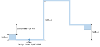
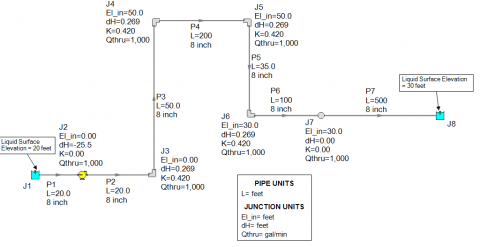
Based upon the fully primed liquid full piping system of Figure 2, this pump has been successfully sized at 1000 GPM and 25.5 feet of head. Again, here is where the problem lies which is very important for the engineer to understand...When the system has not yet been primed and there is no siphoning effect to help the liquid flow through the system, then the pump needs to be able to at least provide enough head in order to overcome the highest elevation head when priming the system.
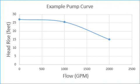
In this particular system the elevation change between the liquid surface of the supply reservoir and the elbow at the top of the riser means that the pump must be able to provide at least 30 feet of head to prime the system. If the example pump curve as shown in Figure 3 is the pump that is selected for the system, it will certainly deliver 1000 GPM at 25.5 feet of head when the system is fully primed. However, because the shut-off head is only about 27 feet, this particular pump will never be able to overcome the 50 foot elevation change.
In order to analyze the system to see if the resulting pump curve can deliver the flow over the 50 foot elevation change, the system would need to be modeled differently because AFT Fathom assumes all pipes are liquid full. Figure 4 shows how the system is split at the end of the riser with a new boundary condition at 1 atm. This model represents a scenario where you would be checking to see if the selected pump can fill the system before the siphon effect can provide any assistance.
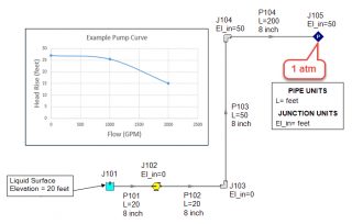
Running the model as shown in Figure 4 would cause reverse flow through the system based on AFT Fathom's liquid full assumption. In AFT Fathom, the assigned pressure junction at the discharge boundary would represent liquid at atmospheric conditions or pressurized conditions if the discharge tank was pressurized. That is why the model would predict reverse flow. But in reality, this just means that the selected pump cannot overcome the elevation change in order to prime the system. The maximum height that the pump would be able to raise the fluid in the pipes to would be 27 feet above the liquid surface of the supply reservoir. Figure 5 shows the reality of the situation at hand where the selected pump curve cannot prime the system.
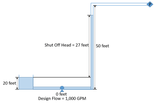
In order to prime the system without a booster pump, the selected pump needs to be able to generate at least 30 feet of head at low flow rates. When the system is primed for the first time, the pump does not necessarily have to operate at the design flow rate. As long as the pump can overcome the high intermediate points when operating further back on its curve at lower flow rates, then the system can be primed successfully. Although the pump will fill the system at lower flow rates than the original design flow, the pump will still naturally begin to operate at the design point on its curve and the system will operate normally after the system has been filled and the siphoning effect begins taking place.
Figure 6 illustrates the difference in required pump head for overcoming the elevation change for system priming based upon the operating flow rate of 1000 GPM compared to a low flow rate operation at 5% of the design flow for system priming purposes. As you can see, at the lower flow rate for system priming, the pump only needs to provide 30 feet of head.

It is not necessary to try and size the pump at 1000 GPM for both normal operation and system priming because this would oversize your pump for normal operation. In this case, priming the system at 1000 GPM requires 35 feet of head which is 10 feet more than is needed for normal operation. Therefore, when determining the pump head required to prime the system before the siphon effect can assist flow, use a lower flow rate and keep in mind that the pump will not be operating at that low flow rate for very long. Figure 7 shows an example pump curve with an additional data point at the lower flow rate. As you can see, this pump will now be able to overcome the original elevation change to prime the system as well as operate at the original design point when the pipes are liquid full.
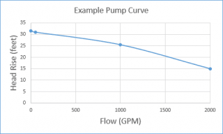
Overall, sizing a pump properly for this type of situation where there is an intermediate elevation change basically requires two data points.
- First data point will be the design flow rate when the pipes are liquid full after the system has been fully primed
- The second data point will be at a low flow rate where the pump will operate further back on its curve to prime the system and overcome elevation changes before a siphoning effect can take place.
To obtain the second data point, split the model of the system at the end of the high elevation point before the elevation starts decreasing again, and assign an atmospheric pressure boundary condition. Then specify a low fixed flow rate at the pump and determine the head rise and that will give you the second data point you need to ensure that your pump will prime the system and also operate properly at the original design point.


Comments 4
Such a system is most likely to experience column separation on pump trip. Therefore it may be necessary to install restriction orifice plates on the downhill section. In addition air valves would likely be fitted at the high point.
Systems have been installed on long pipelines where a turbine is fitted at the end of the downhill section . This would enable energy recovery. Now that Impulse can model turbines things can become a lot more interesting .bIn my experience this system would best be modelled using Impulse in steady state and then the modelling progressed to investigate unsteady state conditions.
Those are some great points Geoff and I absolutely agree that it would behoove the engineer to perform a proper waterhammer analysis after they have sized their pump to see what would happen during the transients. Thank you for your comments!
Problem would be if the pressure at the top of the hill falls below vapor pressure, in that case there will be no siphon and fathom will not be able to caluclate under unsteady flow conditions.
Air valves open at atmospheric pressure, putting an iar valve at the top of the hil (as I read before) will cause air to come into the pipe, air will act as an obstruction and flow at the pipe wll be reduced.
Hi Jose, Thank you for reading the blog and yes, you are correct in that if the static pressure drops below vapor pressure, then cavitation would be present. AFT Fathom actually does identify WHERE cavitation will happen in a piping system, but it does not model it, as cavitation is a highly transient and two phase flow behavior.
AFT Impulse which is our waterhammer software does have the ability to model discrete levels of cavitation very well as long as the cavitation is short-lived, not wide-spread through the system, and the vapor volumes are relatively small in comparison to their computing sections. With that, you can also model vacuum breaker valves in AFT Impulse which will simulate air that would be entering the system when the vacuum breaker valve opens. You can model a special feature in that case with a vacuum breaker valve which will allow you to see how the liquid level inside the immediate upstream and downstream pipes for the vacuum breaker valve will change over time. This way you can track to see how the pipes would drain or fill as the vacuum breaker valve is letting in or expelling air.
Overall, great point Jose and to simulate what you are talking about, be sure to use AFT Impulse, it is a great tool for that!