AFT Blog
Swing Check Valves: As Easy as Pie
What is a Pi-day without a Tips and Tricks blog? That's the $64,000 question today as you are undoubtedly preparing yourself three slices and a sliver of the delicious delicacy. Well the answer is, it's just not as great of a celebration as it could be; so today we are bringing you the scoop on modeling swing check vavles in AFT Impulse!
Last month I published a blog about hydraulic ram pumps and how they work along with tips to model them in Impulse. If you haven’t read that yet, go check it out here. In the blog, I mention capturing the waterhammer effect to pump fluid to higher elevations using check valves. In this application check valves and their opening and closure profiles are extremely important. Yet there is a wider range of applications where this is especially true, surge mitigation. Having the proper check valve to protect important equipment could mean the difference between catastrophic shutdown during a hydraulic transient, or continued safe operation during or after a transient event.
Because we recognize the important role check valves have in protecting your assets, AFT Impulse has had the check valve junction available to help size and model check valves in general for close to two decades now. Legacy users know that we did not always have flow coefficient rate limits present in this junction though. Without these limits, when check valves would close in the past they did so instantaneously, or over one time step. Anyone that is familiar with waterhammer and instantaneous surge pressures will inform you that that is a worst-case scenario, and often not realistic. Enter rate limits; with rate limits specified AFT Impulse check valves no longer close over one time step and provide a clearer picture as to what occurs in these part of your systems as these valves close.
So, what is someone to do if they don’t want to introduce artificially large pressure surges caused by check valves and they don’t know their rate limits? The answer is simple, use our recently introduced inertia model, a swing check valve. As a common equipment configuration for check valves in industry, the swing check valve model also provides a great way to calculate a valve rate over time by letting AFT Impulse complete a torque balance for you. Entering the required information allows users to accurately model the operation, closing and losses of swing-disk check valves.
Among the required inputs shown below are spring constants, disk area, submerged disk weight and information pertaining to the inertia of the disk itself. Other inputs that have a major impact are the valves loss percentage open table. Having this information enables you to make proper use of the check valve model. If not all this information is available to you, we have also included ways to approximate the disk inertia and submerged weight of the disk. From here the torque balance is relatively straight-forward. The torque imparted from the fluid’s movement is balanced with the gravitational toque of the disk and the rotational torque caused by the torsion spring to ultimately determine the angle change of the disk over time. This information is then used in conjunction with a filled-out “Valve Loss vs. Angle Data” table to compute the Cv. It is that simple!
Below are results from a simple model where a transient causes a specified swing check valve to close as the system experiences the effect caused by the initial transient. More specifically, an upstream flow source begins to taper off service and as the flowrate slows down, the check valve must close to prevent the downstream reservoir from draining. The simple model layout is illustrated in Figure 1 here.
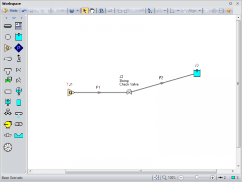
Figure 1 System layout using swing check valve
Figure 2 below shows the fluid transient that will cause the check valve to close. Note, hydraulic transients can have impacts in complex systems from portions of the system that would otherwise be understood to be independent. AFT Impulse allows you to model your system completely to account for this and to avoid overlooking these interactions. In this model, however, the system is relatively simple.
![]()
Figure 2 Transient Event specified in AFT Impulse
The required input information of the valve itself is shown here in Figure 3. Most swing check valve vendors should be able to supply you with this information for your modeling purposes, especially if your project is still in the design phase and you are sizing check valves.
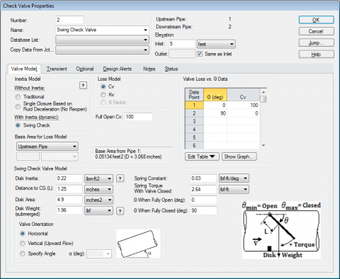
Figure 3 Property window of the check valve when the swing check valve is selected
After the valve begins to change position, a simple graph of the valve’s flow coefficient over time will clearly show the performance of the valve, see Figure 4. Note how the valve is not fully open even at the initial flowrate into the reservoir and how the valve begins to partially open again just before closing for the rest of the simulation. Additionally, the valve closure itself is not linear and in fact exhibits wave-like behavior when closing. Figure 5 although very similar, shows the volumetric flowrate through the pipe downstream of the valve. As pressure waves between the reservoir and the closed check valve continue to propagate along the discharge, the outlet of the pipe will show this through oscillation, Figure 5.
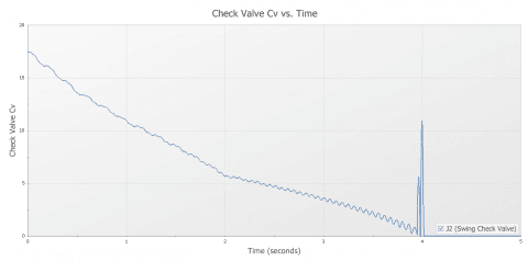
Figure 4 The Cv vs. Time graph for the swing check valve
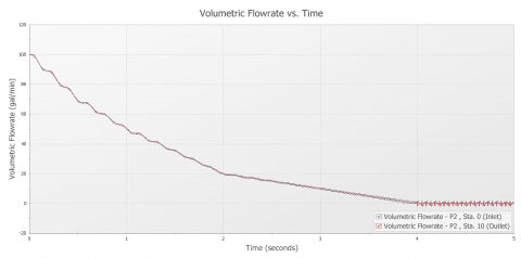
Figure 5 Volumetric flowrates over time of discharge pipe inlet and outlet
As stated previously in this article, check valve operation is a crucial part of safety and surge mitigation. In some rare applications, it is the driving mechanism. For these reasons the importance of properly modeling check valves in AFT Impulse should not be understated. The above model is a quick and simple demonstration of the power that the new inertia model, topping off the check valve junction. Next time you find yourself looking for a more detailed check valve solution, model a swing check valve in your system.
Check out our product page here to learn more about AFT Impulse. The learning center contains serval video tutorials and case studies published using AFT Impulse. Call us today to learn more about using AFT Impulse and swing check valves!
Comments