AFT Blog
Estimating Pump Inertia, Specific Speed, and Four Quadrant Data within AFT Impulse 5
An excellent new feature of AFT Impulse 5 is that it is possible to estimate the pump inertia, specific speed, and four quadrant data sets directly within AFT Impulse 5! No more need to perform external spreadsheet calculations for these estimates.
In addition to that, AFT Impulse 5 can use the entered pump and power/efficiency curve to perform these estimates which makes things much easier and efficient!!
First step is to enter pump curve data and generate the curve fits as shown in Figure 1.
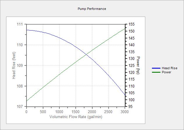
Figure 1: Pump Performance Curve from Entered Data
Next, click on the "Transient" tab of the Pump Property window and pick a pump transient model. This example will use the "Trip With Inertia - Four Quadrant" transient model. As you can see in Figure 2, the fields for Rated Pump Speed, Rotating Inertia, and the Four Quad Data Source are essentially blank.
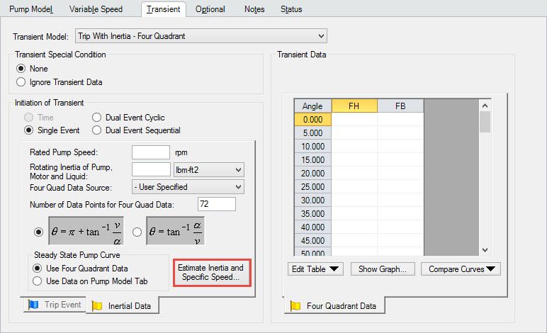
Figure 2: Choose Pump Transient Model and Click "Estimate Inertia and Specific Speed" Button
Simply click on the "Estimate Inertia and Specific Speed" button from Figure 2. The "Estimate Rotating Inertia and Calculate Specific Speed" window will show up and although it contains lots of information, the amount of input required by the user is MINIMAL!
First, enter a rated pump speed in RPM. The rated speed of the pump is the 100% operating speed for the pump that can be found on the manufacturer's data sheet.
Next, you can manually enter the head rise, volumetric flow rate, and Efficiency values at the Best Efficiency Point manually. Or, simply click on the "Get Data from Pump Curve" button like in Figure 3 and this will populate these fields for you based upon your pump curve's polynomial curve fits.
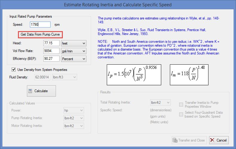
Figure 3: Enter Rated Pump Speed and Click "Get Data From Pump Curve" Button (or manually enter head, flow, and efficiency at the BEP)
Finally, as you can see in Figure 4, after you click on the "Calculate" button, AFT Impulse 5 will estimate the "Total Rotating Inertia" and pump "Specific Speed" for you. To make things even easier and more efficient, you can enable the options to "Transfer Inertia to Pump Properties Window" and to "Select Four-Qudrant Data based on Specific Speed".
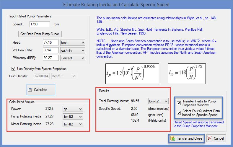
Figure 4: Power, Inertia, and Specific Speed Values Can be Calculated and Transferred to the Pump Properties Window
This will then populate all the required fields of Figure 5 on the Transient tab of the Pump Properties window in order for AFT Impulse to perform its transient calculations.
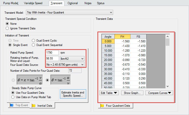
Figure 5: Pump Transient Properties are Fully Specified and Ready for Transient Calculation


Comments 5
this calculation works for Displacements positive pumps inertia too?
Hi Horacio, the pump inertia estimations in AFT Impulse 5 are specifically for centrifugal pumps and are not applicable to positive displacement pumps.
Thanks
Hi, Maybe do you know how complete "Trip event" part?
Hi Arturo, there are a number of examples in the AFT Impulse Examples Help File that will walk you through how to model a pump trip for a system. You can work through those and it should help answer your question.