AFT Blog
Learn About the Acceleration Head and How To Model It
The pistons, or diaphragm of a reciprocating (positive displacement) pump causes a cyclical variation, typically in some sinusoidal form, of both flow in pressure in a piping system. The magnitude varies, depending on the type and design of the pump.
What is acceleration head? Acceleration head is the energy required to change the velocity of the liquid in the system from an at rest, or zero condition, to some non-zero value.
To help us understand acceleration head a little more clearly, you could compare it to a race car. In a drag race, the race car will accelerate to some maximum velocity, and then decelerate back to zero. The car does this by adding and removing energy using the engine and the brakes. Similarly, it takes energy to accelerate the liquid in a piping system. In another analogy, consider a car traveling across a city. In one case, the car is driven on an interstate highway at a constant speed. It takes a certain amount of energy to overcome the road and mechanical friction to maintain that constant speed. But if the car was driven on the city streets, having to stop and go at every stoplight along the way, the trip will take a lot more energy, and gasoline, due to the constant acceleration and deceleration of the vehicle.
Traditional friction analysis of flows in pipes is based on constant, steady-state flows, as you would find in centrifugal pump flow. When starting a cp, there is a peak power requirement that occurs due of the extra energy required to accelerate the liquid from a zero velocity to a steady-state flow velocity.
In the case of reciprocating pumps, the flow is not true steady-state flow, but is continually accelerating and decelerating. This continual change in fluid velocity requires more energy, or acceleration head, so traditional friction loss models may not be completely accurate when performing flow analysis.
The fluctuation of flow and pressure caused by the acceleration head can be mitigated downstream of the pump by locating a flow dampener near the discharge of the reciprocating pump. A flow dampener is a pressurized gas accumulator which absorbs excess energy by compressing the gas in the accumulator, and absorbing additional fluid volume during the acceleration phase of the piston stroke. As the piston stroke causes the flow to decelerate, the excess pressure in the flow dampener causes the liquid that has accumulated to flow out of the dampener, and into the piping system. The flow dampener decreases the fluctuation of the fluid velocity downstream of the pump, resulting in a lower total energy requirement, and achieving steady-state flow.
Overcoming acceleration head is relatively easy on the discharge side of a reciprocating pump, because you have the energy, or pressure, of the pump itself to work with. Acceleration head can be overcome by simply supplying the additional power, or by channeling the excess flow into a flow dampener, so it can be released into the system again, maintaining a constant flow situation.
Dealing with acceleration head on the inlet side of a reciprocating pump can be more problematic, because the only energy available to work against it is whatever the supply pressure happens to be. One must be concerned about low pressure situations occurring on the inlet side of the pump. If the inlet pressure for the pump drops too low, it can cause performance issues, and damage the pump if internal cavitation occurs. This is especially true of situations with relatively long suction piping leading from the fluid source to the pump, due to higher frictional losses in the piping. The cyclical nature of reciprocating pump flow can aggravate this issue, due to the extra energy required to constantly accelerate and decelerate the flow.
Using a method similar to a flow dampener, an inlet stabilizer can be used to mitigate the acceleration head on the inlet side of the pump. In contrast to the flow dampener, which is a pressurized accumulator, anc is an accumulator that would typically be under vacuum. As the flow in the suction line decelerates, liquid is accumulated in the inlet stabilizer. Then the flow the begins to accelerate, the liquid in the inlet stabilizer is released back into the system. In this way, only the liquid in the inlet stabilizer is accelerated, rather than all the liquid in the full length of the suction piping. This reduces the effect of the acceleration head, preventing low pressure issues at the pump inlet, preventing performance issues and cavitation.
The ANSI standard ANSI/HI 6.1-6.5-2015, Reciprocating Power Pumps for Nomenclature, Definitions, Application, and Operation defines a method for calculating the acceleration head in suction lines for reciprocating pumps.
Using Fathom 10 to model the acceleration head
AFT Fathom 10 has incorporated this standard calculation for reciprocating, or positive displacement pumps. If pump acceleration head is added to the Pump Summary output in the Output Control window, AFT Fathom 10 will automatically determine the acceleration head in the pump suction piping.
Being able to directly calculate the suction acceleration head, and display it as an output parameter will simplify the task of designing the pumping system to account for this additional pressure requirement, resulting in more efficient pumping systems, with fewer maintenance and operational issues.
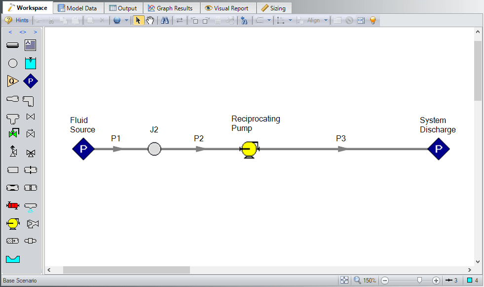
Below are few examples from an AFT Fathom 10 model:

Pipe flow analysis model of acceleration head with a reciprocating pump

Output for AFT Fathom showing the applied standard, and summarizing the acceleration head calculations in the suction piping.

Pump summary in output in AFT Fathom output showing total calculated acceleration head.


Comments