


AFT Blog
Welcome to the Applied Flow Technology Blog where you will find the latest news and training on how to use AFT Fathom, AFT Arrow, AFT Impulse, AFT xStream and other AFT software products.
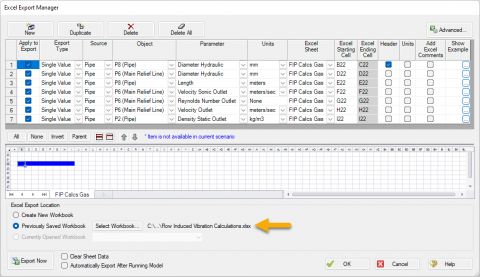
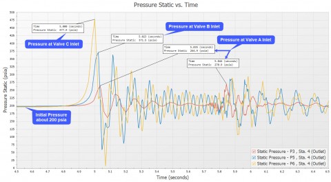
The Opposite of Good Vibrations - Evaluating FIV, AIV, FIP Guidelines from AFT Fathom and AFT Arrow
Learn how to use AFT Fathom and AFT Arrow to help calculate the Likelihood of Failure (LOF) for Flow Induced Vibration (FIV), Acoustic Induced Vibration (AIV), and Flow Induced Pulsation (FIP) in accordance with Energy Institute Guidelines to avoid v...
What Is Transient Analysis?
You're tasked to perform a transient analysis of a piping system and it would be really helpful if there was a good software tool out there to help you. Well, you've come to the right place because AFT has great solutions! ...

Know Your Pump & System Curves - Part 3
In the final "Know Your Pump & System Curves" blog series, I am going to discuss the complexities behind pump vs. system curves for systems with pumps in series and parallel configurations. Multiple pumps in series configurations are relatively s...

Digital Twin – Identical or Fraternal?
When I was a child, I was jealous of twins. I thought how cool it would be to have a twin. I had twin cousins a few years older than I was that I saw on a frequent basis. I always got them confused. Which one was Roger, and which one was Ronny? A buz...
Using “Specified Heat Rate In Constants” for the thermal model of heat exchangers can often cause problems in system models. The reason why is because this thermal model type causes the heat exchanger to act like an “assigned heat input” junction as does an assigned flow junction does for providing constant flow rates. Another problem is that this thermal model can cause unrealistic temperature changes across a heat exchanger. When the heat rate is specified and the mass flow rate and heat capacity are calculated based on the system solution, the temperature change will be whatever is required to maintain the...
6699 Hits
Many of you probably saw in the news that today, Monday, February 20th, is the 50th anniversary of John Glenn’s flight into space. The flight was aboard a Mercury-Atlas rocket dubbed Friendship 7. This historic event was a significant step on the way to the Apollo missions to the moon.
5403 Hits
I have an iPod - to which I am very attached. I hike frequently in the Colorado Mountains near where I live and I can’t do it without my iPod. I can’t work out at the gym without my iPod. I can’t drive my car without my iPod.
6488 Hits
A few months ago I attended a CEO forum in Colorado where a big topic on the minds of the 1000 CEOs in attendance was the state and direction of the US and global economy. The keynote speaker Brian Beaulieu began his presentation with this assessment of the economy from TIME magazine:
4021 Hits
Wherever I go I see change. China is undergoing massive change in a relatively short period of time which has impacted Western nations both positively and negatively – as well as the rest of the world. China’s growth in manufacturing is impacting Australia in a huge way and driving much of the Australian economy through accessing its abundant natural resources.
4109 Hits
In early October, I conducted a 5-day training seminar in Lima, Peru. There were seven different companies represented from Peru and Chile. It is always interesting to see the variety of applications for AFT software and Peru was no exception where many of the engineers are involved in mining operations. Peru is a leading producer of copper, gold, silver, phosphate and potash with over $16 billion in exports in 2009. The engineers at the seminar had a variety of active project responsibilities. These ranged from long transport pipelines, to storage and transfer systems, to refining and process facilities. The course emphasized...
4844 Hits
A frequently asked question at our training seminars - usually during a break or over lunch - is how we came up with the name "Fathom". More completely, the product is named AFT Fathom™ and it is considered by many as the world's leading pipe flow modeling software product.
9445 Hits