


AFT Blog
Welcome to the Applied Flow Technology Blog where you will find the latest news and training on how to use AFT Fathom, AFT Arrow, AFT Impulse, AFT xStream and other AFT software products.
7 minutes reading time
(1401 words)
Where to Start with Pump Startups
Any time a rapid transient occurs in a piping system, there is a chance for unexpected surge to impact the system. Though system shutdowns account for many surge events, pump startups can cause water hammer as well. For this blog I am going to cover the basics of setting up pump and valve transients for the startup case in AFT Impulse 7, as well as some common mistakes to avoid.
The most complex part of modelling this startup case will be setting up the pump, so let's start with the pump properties window. There are two options available for us to model a centrifugal pump startup:
- Speed vs. Time: If you have data available on the speed vs time curve for the pump, then this is the simplest way to define the transient.
- With Inertia Startup: AFT Impulse can calculate the speed vs. time curve using additional information from the user. This option can only be used for starting up a centrifugal pump.
Pump Model tab
With the centrifugal pump option selected, the first thing we will need to do is choose an option under "Reverse Flow", as can be seen below in Figure 1. The simplest option is to choose "Never", in which case we can simply proceed to enter the Pump Curve. This option does not prevent reverse flow, but rather assumes that reverse flow does not happen, therefore reducing the required input in this window. AFT Impulse will warn you if reverse flow actually occurs at the pump, in which case you should return and change this option to "Possible".
If want to use the "With Inertia Startup", or if your system experiences reverse flow, then it is required to select "Possible" for reverse flow. You will need to either choose a four quadrant data set to predict the head with reverse flow, or you will need to model an internal check valve in the pump to prevent reverse flow.
Though I will not delve into defining a four quadrant curve in this blog, you can find more information on this in the "Pump Trip With Backflow – Four Quadrant Modeling" example, accessed by choosing "Show Examples" in the Help menu.
For both startup models, the pump curve will need to be entered on the Pump Model tab. For the "With Inertia" model, note that the Rated Pump Speed on the Pump Model tab and the Power curve data in the Enter Curve Data window will be required.
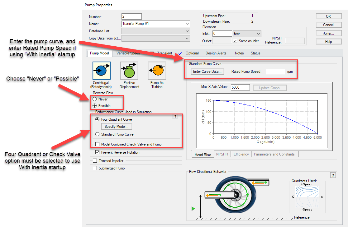
Figure 1: Pump Model tab in the Pump Properties window
Pump Transient tab
This is where we will actually select the startup type and enter the relevant transient data. For the Speed vs Time curve, you will simply need to enter the data into the table as shown in Figure 2.
For the With Inertia Startup, you will need to define the Total Rotating Inertia and the Motor Torque data. I will not go into these items in detail here, though this blog on Inertial Pump Startup provides more information on how these are defined. Note that though the interface looks different for that blog since it was written for Impulse 6, the theory remains the same.
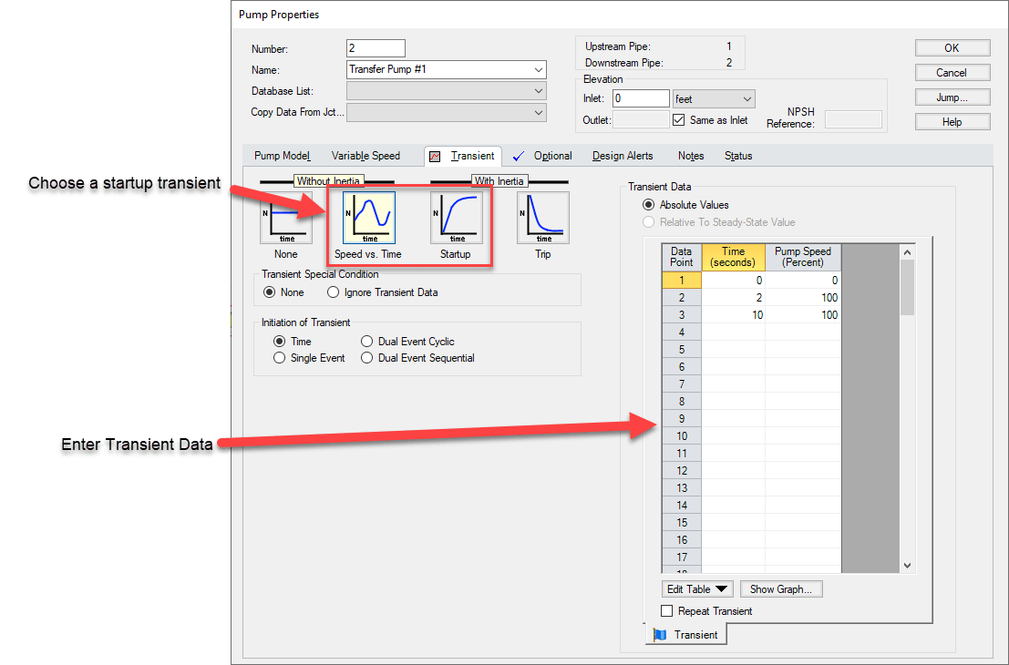
Figure 2: Transient tab in the Pump Properties window
Pump Special Conditions
The last step we must complete to finish defining the pump junction is to set a special condition on the pump. This special condition will be applied for the steady state run to tell Impulse that the pump is off at the beginning of the run. When the startup transient event is triggered, Impulse will remove this special condition and apply the defined transient.
There are two options available to turn the pump off: Pump Off No Flow, and Pump Off Flow Through. For a centrifugal pump startup case the pump will not be blocked to flow, so the "Pump Off Flow Through" option should be selected. The "Pump Off No Flow" option is typically used for positive displacement pump startups.
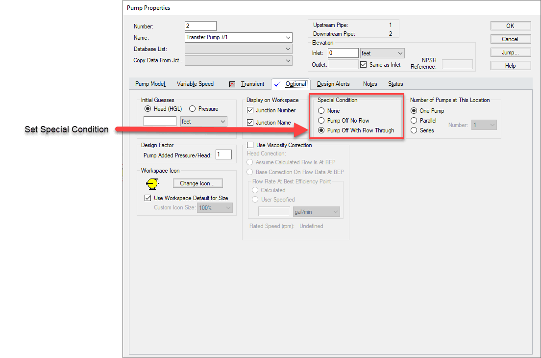
Figure 3: Setting Special Conditions in the Pump Properties window
Besides defining the pump transients for the startup, it is often necessary to open one or more valves in the system as part of the process. While valves assist with keeping the system liquid full when the flow is stopped, opening the valves at startup is crucial to prevent extended dead head at the pump. The timing of these valve openings will affect how the pressure in the system builds up.
Valve Transients
Similar to the pump junction, there are three different tabs we will need to set up for the valve:
- Loss Model – The value entered on the loss model tab should be the fully open loss value, or the loss value for the valve at the end of the transient run. Impulse will produce an error message if the loss value is not equivalent to the final loss value entered in the Transient data tab.
- Transient – We will need to define the initiating event and enter the loss vs. time data on the tab. For the valve opening the valve must be closed at time zero, then will increase from there. The Cv or Kv will be 0 when the valve is closed, while the K factor will be -1. For more details on setting up transients,check out this blog on transient events.
- Optional – On the Optional tab the Special Condition needs to be set to closed. Like with the pump, this will define the initial state of the valve, which will then change as the transient event begins.
Addressing Common Errors
Once the system is run, there are a few common errors that you may see when running the model. Here are a few tips to avoid these common mistakes:
1) "One or more pipes did not have a steady state solution…"
This message will pop up at the beginning of the transient run if you have a section of pipes isolated between closed junctions, such as the pipes between the closed valves in Figure 4 below. To avoid this, you will need to define the steady state pressure for this region. Go to the Optional tab in one of the Pipe Properties windows, and set a Stagnant Region Steady-State Pressure. Doing this in one pipe will allow Impulse to calculate the pressure throughout the isolated section. If the pressure you defined is not reasonable for the system you may get artificial transient warnings in the model, so be careful when defining this.
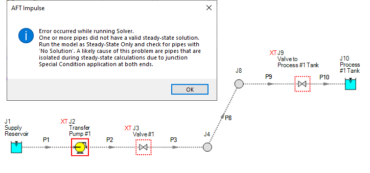
Figure 4: Example of a model where a Stagnant Region Steady-State Pressure needs to be defined
2) Artificial Transients
There are several different cases that may cause artificial transients. I will not cover all of them here, but one of the simpler cases that may come up is an artificial transient due to very small changes in the flow rate. Though they result in a large relative magnitude change, this small change will have little effect on the results, and can often be ignored. Transient Control provides an option to ignore artificial transients from small flow rates, as shown below in Figure 5. For more information on other artificial transients, see this Artificial Transients blog which provide more troubleshooting tips.
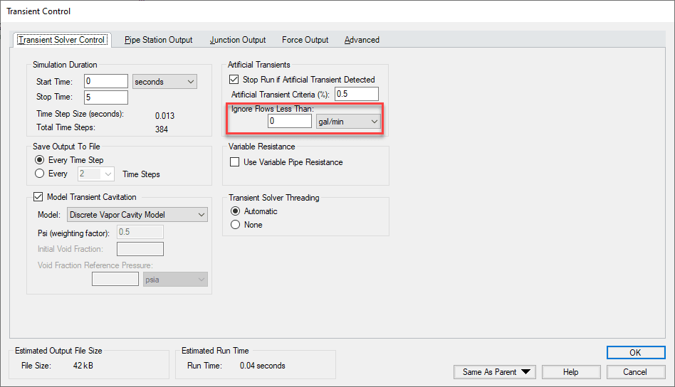
Figure 5: Setting the option in the Transient Control window to ignore artificial transients caused by low flowrates
3) Use Variable Pipe Resistance
After running the model, you will likely see warnings like those shown below in Figure 6. Typically, Impulse uses the friction factor calculated during the steady state for the whole transient run. However, for startup cases this friction factor may change drastically from the steady state to the transient as the flow increases from zero to the normal operation flow rate. It is therefore good practice for startup cases to turn on Variable Pipe Resistance in the Transient Control window for at least the final run. This will have a minimal impact on the results in many cases, though it may have a large impact in some situations. Check out this blog for more technical details on this.
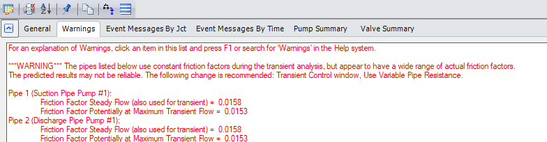
Figure 6: Warning message that the transient friction factor differed substantially from the transient friction factor due to Variable Pipe Resistance calculations being turned off
Though modelling pump startups may seem challenging at first, following these guidelines can help to make this process quick and straightforward.
Comments