


AFT Blog
Welcome to the Applied Flow Technology Blog where you will find the latest news and training on how to use AFT Fathom, AFT Arrow, AFT Impulse, AFT xStream and other AFT software products.
10 minutes reading time
(1908 words)
Q&A: Calculating Transient Forces for Pipe Stress Analysis
In June 2020, AFT's Reinaldo Pinto presented the webinar Calculating Transient Forces for Pipe Stress Analysis. The webinar focused on generating unbalanced forces due to surge in AFT Impulse and exporting them to CAESAR-II. During the webinar, 28 questions were asked. Below are the responses.
Download the presentation: www.aft.com/webinar/History_Spectrum_Analiysis_Presentation.pdf
1. Please explain how to decide the nodes for force calculation. If there are multiple elbows intern change direction changes in pipe routing then do u suggest to estimate the out of balance force for each pair of elbow?? Or only for vertical or horizontal portions of the pipe.
Answer: There is really no straight answer for this, since the criteria on what the pair of elbows are to be included in the analysis will depend on many factors, such as: magnitude of the overpressure, diameter of the pipe, pipe material, etc.
As a rule of thumb, pair of elbows that are very close (less than 2 m) are less critical than pair of elbows that have longer pipe run. This is due to the fact that imbalance force will last longer in pair of elbows with longer pipe run.
2. There is lot of debate on while doing static analysis whether to consider DLF factor of 2 again on dynamic forces estimated by AFT impulse?
Answer: you are correct, there is a lot of debate on whether using a DLF factor of 2 is non-conservative. There has been no conclusion on this discussion, so the DLF number to use for the Static Equivalent is still 2.
3. Do the Stresses can be reduced by increasing distance between the elbows and valves?
Answer: Increasing the distance between elbows could make the situation worst, since it makes the duration of the imbalance force longer in this section.
4. Should instantaneous peak transient forces be used for anchor loading design? Or is load applied and resolved so quickly that piping does not have time to react?
Answer: Yes, the anchors should be able to handle the peak forces.
5.While modeling in AFT Impulse do we have to take into account all the bends ? If yes does this mean after the pipe routing is fixed we should do the dynamic analysis.
Answer: The only accessories you need to model in AFT impulse, are those that constitute wave reflection points such as: orifice, area reduction, valves, tees, etc. In general, if the loss of the component is "small enough" with respect to the overall system pressure drop and magnitude of pressure waves traveling in the pipes, which is usually the case for bends, then it is acceptable to either not model the bends at all, or lump the K factors into the pipe's "Fittings & Losses" which evenly distributes the pressure drop from the total K factor of all lumped components across the entire pipe length. That is why a transient analysis can be performed without having the piping routing, to determine if there is a potential problem due to waterhammer and implement a solution before the problem occurs.
6. What can be the adverse effect of increasing the closing time of the valve have adverse effect on the fluid?
Answer: Increasing the valve closing time is always the cheapest option, but it might be limited by process requirement e.g. a minimum closing time due to environmental regulations. Another reason for not been able to use the valve closing time solution, is due to the impossibility of assuring the exact closing time e.g. when the closure of the valve will be done manually.
7. The X, Y & Z are the same as global axes of Caesar II?
Answer: Yes, the X, Y & Z coordinates specified in AFT impulse should be the same as the global axes used in CII.
8.What about 3rd direction X?
Answer: All three directions (X, Y & Z) can be specified in AFT Impulse 8
All three directions (X, Y & Z) can be specified in AFT Impulse
9. Does the angles between pipes affect the results? where we should enter the angles?
Answer: Yes, angles between pipes does affect the result, mainly because the change in elevation will change the friction loses in the system. This angle is specified, when you create the model in AFT Impulse, when you enter the elevation of the junctions to whom each pipe is connected to.
10. Have you seen water hammer problems in systems with rupture disks?
Answer: Rupture disks can be a potential source of waterhammer, so they need to be model. This would be similar to a tube rupture in a heat exchanger, where there is a sudden pressure increase in the shell side due to the rupture of the tube, that generates a pressure wave that needs to be considered when designing the heat exchanger protection system.
11. For complicated systems with dozens of legs, how would you screen them to decide which elements are worth analyzing in more detail?
Answer: See response to Question 1
12. Is it necessary to prepare model in Isometric drawing mode to understand and match the directions with CAESAR-II model?
Answer: It is not necessary to prepare model in Isometric drawing mode, ISOMETRIC drawing was used in the webinar to help the attendees understand better. The type of drawing used, whether ISOMETRIC or 2D, does not affect the result of the calculated forces or how it matches the CII model.
13. Whether Spectral or Time History Analysis., process is same in AFT Impulse for generating forces?
Answer: Yes, it is basically the same. The only difference is when generating the force file in AFT Impulse to export be exported to CII:
Spectral: Time units is Seconds and all pipe segments where the force is going to be analyzed shall be created in one file.
Time history: Time units is Milliseconds and all pipe segments where the force is going to be analyzed shall be created in separate file
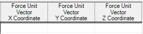
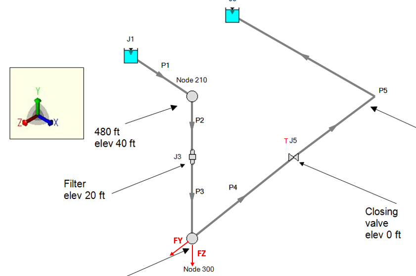
14. What values to put in X, Y, Z coordinate vectors?
Answer: See fig below
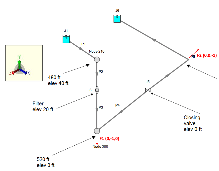
What values to put in X, Y, Z coordinate vectors
15. Could the analysis done for non 90 degree elbow for example 45 deg elbow? if Yes, how to do it/transfer to CAESAR II?
Answer: See fig below
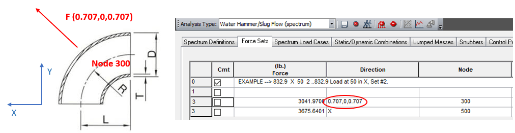
Analysis for a 45 degree elbow
16. Do you need to specify the original surge analysis model in a specific way to include the calculation of the force data?
Answer: No need to specify the original surge analysis model since AFT Impulse will generate a force file specifically for the pipe stress program to be used (see below fig). Force data can also be exported to an excel file if needed.
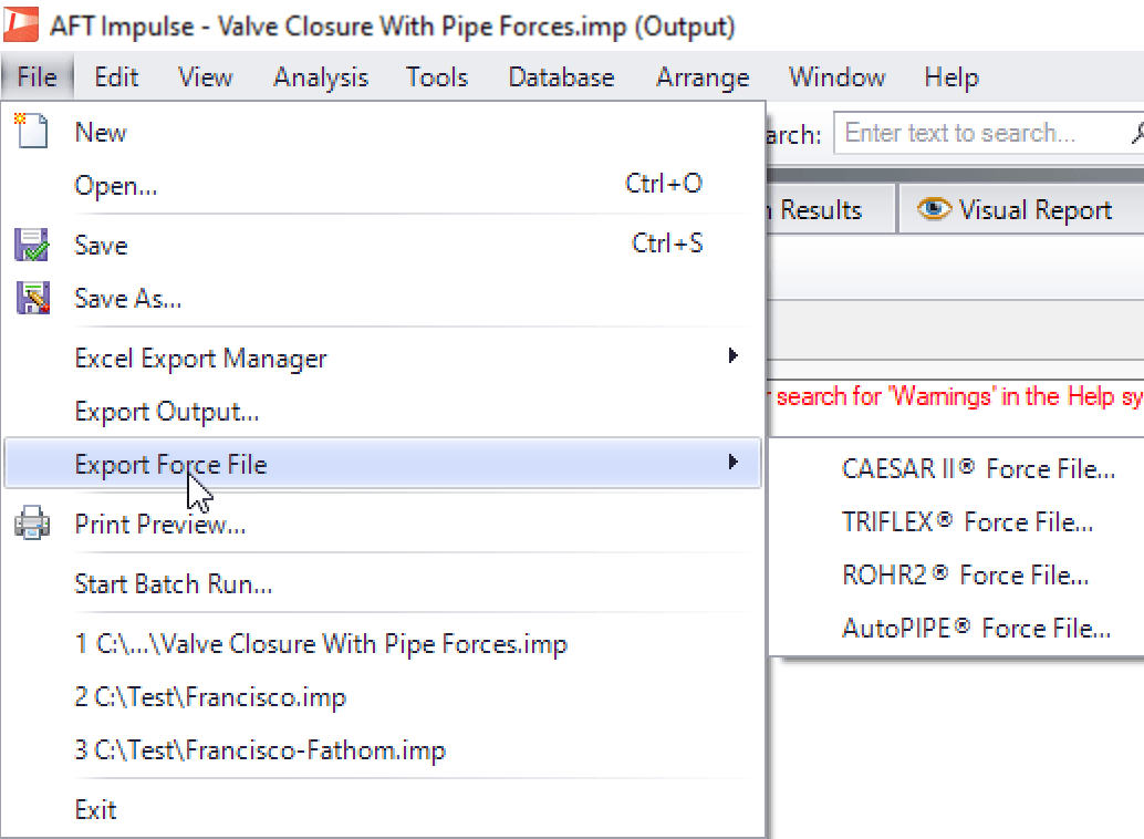
AFT Impulse will generate a force file specifically for the pipe stress program to be used
17. The reason behind 33Hz is not very much clear ??
Answer: Any mechanical frequency below 100 Hz is considered a vibration mode that requires low energy to be excited. An imbalance force created by a waterhammer, is a fast-acting force that perturbs several mechanical vibrational modes at the same time. When you calculate the resultant stress created by the waterhammer, you want to include as many low energy modes as possible, that is why you change the frequency cutoff from 33 Hz to 100 Hz.
18. Is bend considered in both pipe segments where there is direction change or bend is considered only in one pipe segment?
Answer: Both pipe segment connected to the elbow should be considered, see fig below for details.
Both pipe segment connected to the elbow should be considered
19. If the model has column separation, is it possible to calculate the forces?
Answer: yes, it is possible to calculate the forces if there is column separation (cavitation). Hydraulic Transient Forces (HTFs) frequently rely on the comparison of pressures in two distinct locations at a particular time. Inaccuracies in wavespeed and timing due to the presence of cavitation can result in inaccurate HTFs when using force pairs (i.e., elbow pairs), even when the pressure magnitude is considered reliable. AFT recommends reading the following guidelines when calculating forces with cavitation.
20. If the max code pressure is not exceeded in a hammer event, do you still need to analyze the stress for B31.3?
Answer: Yes, you still need to analyze the stress for B31.3 even though pressure is not exceeded in a hammer event. The reason for this is that the design pressure is established in the circumferential direction (hoop stress), and the dynamic load due to hammer would be compared to the allowable in the longitudinal direction.
21. Do you provide a PHD Certificate to the attendees?
Answer: Send your request to Julie Bedsole (This email address is being protected from spambots. You need JavaScript enabled to view it.)
22. In the frc file, if the forces have negative signs, then there are no spaces between time & force values, user had to add spaces manually, is it still the case?
Answer: This was fixed, user no longer need to add spaces manually in the frc file
23. For a large system, there are many pairs of bends/elbows, for the force sets to be imported to CII, what is the limit to the large data import to CII?
Answer: We haven't had a limit regarding the number of force sets that can be exported to CII. The limit for CII is established in the data size of each force sets (2000 points). AFT Impulse will give you a warning message when this limit is exceeded, and it can be fixed by limiting the simulation time to be exported.

The limit for CII is established in the data size of each force sets
24. In addition, is there a criteria to selectively judge which pairs of elbows will not have a concern at all, so it is not required to create a force sets?
Answer: There is really no straight answer for this, since the criteria on what the pair of elbows are to be included in the analysis will depend on many factors, such as: magnitude of the overpressure, diameter of the pipe, pipe material, etc.
As a rule of thumb, pair of elbows that are very close (less than 2 m) are less critical than pair of elbows that have longer pipe run. This is due to the fact that imbalance force will last longer in the longer pipe runs.
Presenter's Contact Information:
Reinaldo Pinto, Technical Sales Director
Applied Flow Technology
This email address is being protected from spambots. You need JavaScript enabled to view it.
Comments