AFT Blog
When to Begin? Time and Events in Transient Studies
To define any transient event in AFT Impulse or AFT Fathom XTS the application must know when it begins. To do so, the user should know how time and event logic is approached in AFT’s transient solvers. In this article, we will discuss the three different time bases used in the applications, the selection of a single or repeating event, and the many possible triggering events that can start the user defined transient.
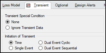
The user defines these items in the Initiation of Transient section of the junction’s Transient tab. The requirements for each junction can vary, but the general approach applies to all transient events.
For the purposes of this article, it is assumed that the Transient Data controlling the event is completely and correctly defined – the discussion here will be focused only on the initiation of the event.
Before diving into events, let’s discuss time. It is important to recognize the difference between Absolute Time, Simulation Time, and Event Time.

Above, the three different time bases are shown in one of many possible configurations. Absolute Time is a fixed reference time that is not changeable – every other time is in some way based off this reference. All times reported in the Output are Absolute Time.
Absolute and Simulation Time are often identical. The simulation Start Time is set in Transient Control to an Absolute Time of zero seconds by default, but it could be non-zero. In Figure 2, the Simulation Start Time is set to a value of 2 seconds – the entire Simulation Time timeline is shifted forward 2 seconds.
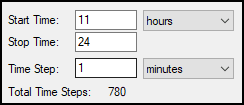
As an example, if an engineer is using AFT Fathom XTS to study long term effects over the course of a day – it may be useful to start the simulation at a certain time of day, say 11am. That is, the Start Time could be set to 11 hours. This shifts the entire simulation to occur later in the Absolute Time base. Assuming the inputs are consistent, changing the Start Time does not change the results other than the specific values for time.
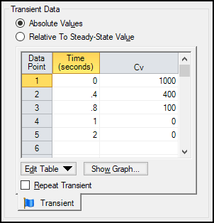
Event Time refers to the time defined in Transient Data – this could be equal to Simulation Time (and Absolute Time) depending on how the event is defined. For example, all three time bases will match for a pump trip event starting at the beginning of a simulation with Start Time equal to zero. However, the event may not start until a certain system condition is met and zero Event Time could be well into the simulation.
In Figure 2, the event starts one second after the beginning of the simulation. However, there could be many reasons for this – the event could be set to start exactly one second after the simulation start, it could be starting at an Absolute Time of 3 seconds, or it could be starting because a parameter elsewhere in the model met its target value at that time.
Now that the background is out of the way, the first option to consider is what type of event you are defining. There are four possible options, although not every option is available for every junction or model:
- Time
- Single Event
- Dual Event Cyclic
- Dual Event Sequential
In a few cases, such as a Check Valve transient, the only option is Time so no selection is shown. The Time option simply uses the values defined in the Transient Data directly. A row that defines a value at 5 seconds will apply that value at an Absolute Time of 5 seconds.
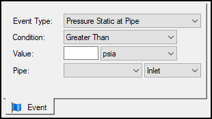
Selecting Single Event brings up the Event tab requiring the definition of a logical trigger to start the transient:
- Event Type
- Condition
- Value
- Location
Note that in some cases the Event text will sometimes change to reflect the model – for instance, a pump startup denotes that this is the Start Event.
There are numerous Event Types available – these selections measure some property within the simulation. Only applicable Event Types will be displayed.
| Check Valve State | Control Valve State | Cv |
| EGL at Pipe | EGL Diff. at Junction | EGL Diff. Between Pipes |
| HGL at Pipe | HGL Diff. at Junction | HGL Diff. Between Pipes |
| Kv | Mass Flow Rate in Pipe | Pressure Stag. Diff. at Junction |
| Pressure Stag. Diff. Between Pipes | Pressure Stagnation at Pipe | Pressure Static at Pipe |
| Pressure Static Diff. at Junction | Pressure Static Diff. Between Pipes | Pump Speed |
| Relief Valve State | Reservoir Liquid Height (XTS) | Reservoir Liquid Volume (XTS) |
| Reservoir Surface Elevation (XTS) | Reservoir Surface Pressure (XTS) | Spray Discharge Outflow |
| Surge Tank Gradeline (Impulse) | Surge Tank Liquid Height (Impulse) | Time Absolute |
| Time Difference | Valve Open Percent (XTS) | Velocity in Pipe |
| Volumetric Flow Rate in Pipe |
Condition defines the logical relationship between Event Type and Value - the specific magnitude of the Event Type parameter at the Location. The Location changes dynamically based on the Event Type that has been selected.
Once the logical test specified is met, the actual event specified in the Transient Data table is begun.
The next option, Dual Event Cyclic, requires the definition of two events – a First Event and Second Event as well as corresponding Transient Data for each event. The definition of each of these events is identical to the definition of a Single Event.
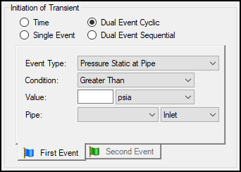
Dual Event Cyclic will continue monitoring both triggering events throughout the simulation and will apply the corresponding transient data when the conditions are met.
To use AFT Fathom XTS as an example – this is very useful to define a pump control to fill a supply tank – a pump can be defined to turn on when the liquid level in a tank drops below a minimum level as the First Event, filling the tank. The Second Event would then be defined to turn the pump off when a maximum level is reached. Over a long simulation with these criteria, the user may see the liquid level continually rise and fall in accordance with demand.
Finally, a Dual Event Sequential selection can be made. The required information for this event is identical to Dual Event Cyclic. The difference is that the two defined events are only applied once. That is – after the second event is complete, no more transients will be applied even if the conditions are met.
One common situation where this is useful is tripping and restarting a pump in AFT Impulse. Pump tripping is often a one-time event rather than a function of normal operation, so it may not be desirable to define this as a cyclic event.
Occasionally you may wish to define an event that requires multiple conditions be met. While a multiple condition event cannot be directly specified, by creating a “sub-model” in a creative way such conditions can be implemented. You can read about making your own “Logic Gates” here: It’s Only Logical
With these options, the engineer has many tools at their disposal to implement a controlled system within AFT Fathom XTS or AFT Impulse.


Comments