


AFT Blog
Welcome to the Applied Flow Technology Blog where you will find the latest news and training on how to use AFT Fathom, AFT Arrow, AFT Impulse, AFT xStream and other AFT software products.
6 minutes reading time
(1208 words)
Looking to relieve pressure? Let's talk about Relief Valves in AFT Impulse.
In any complex piping system, one of the most serious scenarios considered during a safety or HAZOP study is over-pressurization. If the pressure in the system reaches a high enough pressure, rupture can occur, leading to expensive repairs, significant system downtime, and even loss of life. In most cases, proper use of relief valves can mitigate or avoid pressure-induced rupture. Fortunately, AFT software can be used to easily and accurately model relief valves in a variety of scenarios, assisting engineers in designing safe and reliable systems.
All three major AFT products – AFT Fathom, AFT Arrow, and AFT Impulse – are capable of modeling relief valves for the conditions each are designed for. AFT Fathom and AFT Arrow can help show if the steady state scenario will ever reach the relief valve set point, and how that system will operate after the relief valve is opened. AFT Impulse can help understand how the valve will behave during both steady state and transient operation, and how the system as a whole will respond to various transient events.
Let's take a look at how AFT Impulse and its transient analysis can be used to understand how relief valves affect the systems they are used in.
To model relief valves, AFT Impulse provides four valve profile templates plus a general profile option that allows the user to specify a unique valve design, and are outlined in red in Figure 1 below. These four profiles include:
- Passive: the valve opens and closes based on pressure forces. Typical passive valves are constructed using a spring to keep the valve closed below the set point and to close it as the pressure is lowered.
- Pilot Operated: the valve opens and closes based on pressure forces. Typical Pilot Operated Relief Valves (PORVs) use a hydraulic fluid on the back side of the valve to hold the valve closed. This fluid can either be a separate system or connected to a remote location in the network.
- Rupture Disk: the valve opens at a set pressure and does not close. Rupture disks are often used when quick response is needed to avert an infrequent but serious over-pressurization scenario.
- Surge Anticipator: the valve opens and closes based on pressure forces. Typical surge anticipating valves are operated similarly to a remote sensing pilot operated valve, with the system working to dampen pressure waves traveling through a system.
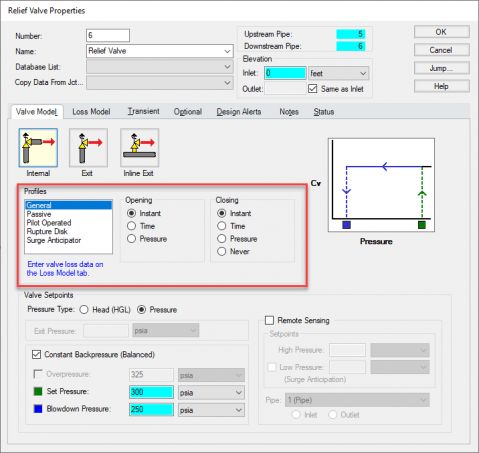
Figure 1: Relief Valve Properties window in AFT Impulse.
The General Profile option allows the user to create their own valve, allowing it to open and close instantaneously, along a defined time-Cv path, or based on pressure forces. With this General Profile option, when the user selects "Time" for the opening or closing profile, they are then able to go to the Transient tab, where they can enter information to define that transient profile.
Below the Profiles section, the Valve Setpoints section allows the user to define operating points of the valve. The Set Pressure defines the pressure at which the valve begins to open, the Overpressure defines when the valve is fully open, and the Blowdown Pressure defines when the valve closes.
Furthermore, all types of relief valves modeled in AFT Impulse can be modeled as either hydraulically balanced (with constant backpressure) or not. When the valve is balanced, the valve mechanism is independent of downstream pressure, and the set points can be defined based on the actual upstream pressure. When the valve is not balanced, the backpressure on the valve is not constant, and the set points are based on pressure differential with the downstream conditions.
The rest of the input for relief valves in AFT Impulse is similar to any other valve junction in the software. Users can input loss modeling information for their valve, allowing AFT Impulse to accurately determine flow through the relief valve while it is open. They can also add in Design Alerts, notifying the engineer if any set of events happens to the valve including it opening or reaching a specific pressure or flow rate.
With these options, virtually any relief valve design can be modeled during transient events, allowing their effects on the rest of the system to be accurately determined. Let's take a look at how different relief valves affect a system in AFT Impulse.
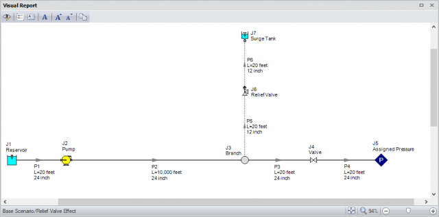
Figure 2: System schematic Visual Output with selected information.
The system we'll look at, depicted in Figure 2 above, has pump J2 trip with inertia 5 seconds into the simulation, while valve J4 closes linearly over the first 2 seconds of the simulation. Notice that pipe P2 is 10,000 feet long, meaning the pressure wave generated in the system takes some time to travel back and forth, allowing us to see pressure surges relatively spaced out.
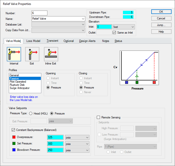
Figure 3a: Example relief valve inputs.
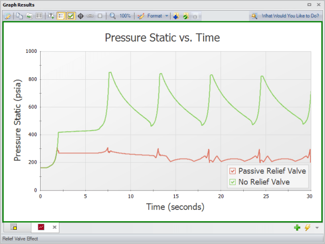
Figure 3b: Static Pressure vs. Time upstream of valve J4 without a relief valve and with a passive pressure relief valve.
Next, let's look at how different types of relief valves affect the system. Figure 4 below, compares two different relief valves: a rupture disk set to 300 psia and the same passive relief valve shown in Figure 3a. As the graph shows, both systems rapidly pressurize and open after only a few seconds. However, because the system with a rupture disk releases most of the system pressure when the system first passes 300 psia, the pressure quickly drops towards the system pressure and experiences substantially reduced pressure variations at later times.
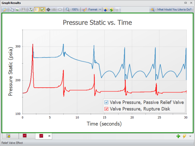
Figure 4: Static Pressure vs. Time upstream of valve J4 for the base passive relief valve and a rupture disk relief valve.
As evidenced by these two examples, modeling relief valves in AFT Impulse gives engineers the ability to analyze and understand which types and designs are best for their system. It allows them to understand how a relief valve will perform in the context of potential over-pressure events, during system design, and before those events happen during operation.
This discussion of relief valve design gives a good starting point for effectively and accurately creating models in all AFT software products. As with any aspect of system modeling, this topic has far more nuance and complexity than discussed here. For further help with relief valves – or any other topic – reach out to AFT's support group at This email address is being protected from spambots. You need JavaScript enabled to view it..
Comments