


AFT Blog
Welcome to the Applied Flow Technology Blog where you will find the latest news and training on how to use AFT Fathom, AFT Arrow, AFT Impulse, AFT xStream and other AFT software products.
8 minutes reading time
(1632 words)
Are you for real? Understanding and Troubleshooting Artificial Transients in AFT Impulse
I tend to reflect on the truly endless list of things I am so grateful for. While this list is by no means exhaustive, some of these things include my loved ones, my awesome job at AFT, the bounty of pumpkin-flavored treats that sweeten up my fall-time snacking options, and of course, AFT Impulse’s detection of artificial transients. While the dreaded Warning message that an artificial transient triggers can cause any engineer’s stomach to turn, I’ll explain why every AFT Impulse user should add this feature to his/her list of things to be thankful for as well.
Let’s start with an explanation of what artificial transients are. Very simply, artificial transients are non-real transient events that happen when the Impulse solver switches from the steady-state solver to the transient solver. Before AFT Impulse initiates the transient simulation, it performs a “zero time step computation” and compares the results at this zero time step to the results from the steady state solver. If the difference in either (or both) pressure and flow exceeds the artificial transient criteria that’s specified in the Transient Control window (see Figure 1), then AFT Impulse will stop the simulation and give a warning. This is very helpful, especially for large models, because the results of a model with an artificial transient are unreliable. Artificial transients must be resolved before the results can be used, so let’s discuss how to locate and fix an artificial transient.

We will use the model in Figure 2 to supplement our discussion of artificial transients.

In this model, a pump transfers water from the upstream reservoir to the downstream reservoir. The pump startup is being modeled, so the pump initially is not adding any pressure to the system. The valve J7 is closed, and it begins opening after the pressure at the valve reaches a certain value. For the purposes of this blog, the pump startup does not start until 1 second after the transient begins. This is an unnecessary step in transient analysis and simply wastes time by completing several timesteps of meaningless calculations as described here, but it is useful in this blog to prove that nothing should be changing (no pressures or flows) in the system for the first second. This is because the transient doesn’t begin immediately. If changes occur in the first timestep before the pump is set to startup, this will indicate the presence of an artificial transient.
When we try to run the model, the Solution Progress window stops the solver from progressing, and it gives the message that artificial transients exist and that the calculations were terminated (see Figure 3).

How do we address this error message? The first thing to do determine where the artificial transient is coming from. Click on the Output button on the Solution Progress window in Figure 3, and observe the warning messages in the Output window that appears. In this model, we see that a pressure and flow artificial transient was detected at the outlet of Pipe P2 and the inlet of Pipe P4 (see Figure 4).

Note that a warning message is displayed in addition to the critical warnings for the artificial transients in Figure 4. Any additional messages should be viewed as potential clues as to why you are receiving an artificial transient. These messages may or may not be relevant to the artificial transient. In this case, the artificial transients are observed in the pipe stations connected to the vacuum breaker valve (a notorious junction for causing artificial transients), and we receive a warning that the vacuum breaker valve is open in the steady-state. From these clues, it is highly likely that the vacuum breaker valve is causing the artificial transient, but let’s do some more digging.
When evaluating an artificial transient, it is most helpful to animate the results. The default setting when an artificial transient is present is to stop the run, but you can (and should) permit the simulation to run in this troubleshooting stage. To do this, return to the Transient Control window and uncheck the box next to “Stop Run if Artificial Transient is Detected”.

The final step before running the simulation with the artificial transient is to ensure that the appropriate pipe data is being saved in order to animate the artificial transient. This is done from the Pipe Station Output tab on the Transient Control window. With larger models, only saving the pipe data for the pipes that are experiencing the artificial transient and a few surrounding pipes is wise in order to prevent the run time from being unnecessarily large. Also note that the artificial transient occurs at the beginning of the transient simulation, so for the purposes of troubleshooting the artificial transient, you can run the simulation only for the first few timesteps to decrease the run time.
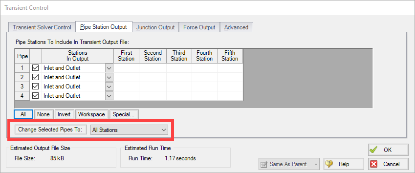
Because our run time is already very short, we will save all pipe stations (Figure 6). After the adjustments to the Transient Control window have been made, run the model. Note that the Solution Progress window still gives a notice that an artificial transient exists (Figure 7), but because the artificial transient is being ignored, it completes its calculations.

Once the run is done, go to the Graph Results tab. Select the profile tab on the graphing section of the Quick Access Panel, and specify the path of pipes to animate. This path should include the pipes in which the artificial transient exists. Because we are seeking to animate the results, specify “Animate Using: Output”, and select the parameter that contains an artificial transient. In our case, both a flow and pressure artificial transient exist, so we will look at the response in both of these parameters using the Stacked Graph feature. Figure 8 shows these parameters specified on the Quick Access Panel. Note that we have unselected the Max and Min values to prevent these lines from obstructing our view of the artificial transient.

Once the graphs have been generated, click on the plus sign once on the Animation Step Controller located above the graphs to show the pressure and flow behavior at the first timestep. To orient yourself to the junction locations along the pipeline profile graphed, also select the “Show Junction Locations” icon. The Animation Step Controller and “Show Junction Locations” are highlighted in Figure 9.

Figure 10 shows the steady-state pressure and flow results. Note that Junction J6 is the vacuum breaker valve.

Figure 11 shows the pressure and flow results at timestep t = 0 + 1 timestep, which is at an absolute time of 0.0023 seconds.
")
Figure 11 reveals the artificial transient, highlighted in red boxes. Because no transient is specified to occur before time t=1 second, these changes in pressure and flow indicate that an artificial transient exists. Because these changes appear in the pipes immediately upstream and downstream of the vacuum breaker valve, and because we received the warning that the vacuum breaker valve is open in the steady state, we can be certain that there is a problem with how our vacuum breaker valve is being modeled. Vacuum breaker valves are the most likely culprit for artificial transients. This is because AFT Impulse assumes that all pipes are liquid-full in the steady-state, unless the partially full pipe feature is being used.
Figure 12 shows the graphs in Figure 11 after some time has passed, but no transients have yet commenced (timestep = 0.9529 seconds).

If you watch the animation, you will see that the artificial changes in pressure and flow continue to propagate throughout the pipeline. This non-real event is what AFT Impulse’s artificial transient detection capabilities prevent.
The most common cause of artificial transients is what we observed in the example discussed: input errors. In this case, the “input error” isn’t an error per se, but it is problematic for AFT Impulse because the steady-state calculations and zero-timestep transient calculations do not match up, which induces the artificial transient. In order to ensure that false transients do not affect results, this discrepancy must be resolved. Another much less common cause of artificial transients is a calculation that needs to be adjusted in the AFT Impulse solver. If you are unable to determine the cause for your artificial transient, please contact our support team.
Note that a very similar, alternative way to analyze artificial transients is by ignoring all transients (this is an option on the Transient tab) and running the model for multiple timesteps. Because all transients are being ignored, any change in pressure or flow can be attributed to an artificial transient.
It is also important to state that the criteria used to detect artificial transients can be adjusted, as shown in Figures 1 and 5. This is helpful in cases such as when there is no flow initially in a pipe, and the first timestep transient calculation determines a negligible but non-zero flowrate.
If you remain unconvinced that artificial transient detection is a feature to be grateful for, listen to how engineers (including AFT’s founder and CEO Trey Walters) found out that artificial transients existed over 20 years ago. Back then, computers were commonly shared among many users, and engineers had to submit their models to a person who ran one model at a time. Hours (sometimes days) later, the engineer would receive the results of his/her model, and it was only at that point that the artificial transient became apparent. If an artificial transient existed, the engineer would have to start the process all over. Today, AFT Impulse allows the nearly instantaneous detection of artificial transients. This means that AFT Impulse users will not waste appreciable chunks of time running the model, only to discover that the model contains an artificial transient and they must start all over. Now…artificial transient detection…that’s something to be grateful for!
Comments 2
Thank you Erin for drawing our attention to this issue.
One thing that I miss here is HOW to resolve the issue. How to specifically get rid of the artificial transient?
You mentioned: "this discrepancy must be resolved", but in the example you provide, how would you resolve it? What needs to be done to the vacuum breaker, to adjacent pipes to get rid of the issue? And if nothing can be done to the model (inputs are correct), how do we go further?
Thanks for elaborating.
Alan
Thank you for taking the time to read my blog and to give me some feedback!
The model discussed in this blog involves a somewhat tricky situation in AFT Impulse. This is because this configuration stretches the abilities of AFT Impulse as discussed below, especially with respect to handling air in liquid systems and getting around the issue of an unsteady initial condition.
To remove the artificial transient in this model, an initial gas mass should be input into the vacuum breaker valve/gas release junction. This resolves the artificial transient that Impulse detects because, with the initial gas mass input, Impulse knows that the vacuum breaker valve is open in the steady state and it does not attempt to change its position as it switches from the steady state calculations to the transient calculations. While I’d love an answer that was that simple, there are several considerations to be aware of with this response.
First of all, as soon as the transient begins, air will enter the vacuum breaker valve to ensure that the pressure is kept at atmospheric pressure. Therefore, bypassing the artificial transient is more of a special condition that was allowed in Impulse to try to approximate the needs of some users wanting to model systems with vacuum breaker valves open initially. To get this model to start out as close to steady state as possible, both pipes connected to the vacuum breaker valve could be modeled as partially full, and the liquid level in these pipes could be adjusted until the pressure at the vacuum breaker valve was at or very near 1 atm. Additionally, keep in mind that modeling the air in the system also requires simplification in Impulse because Impulse cannot model two-phase flow, so any air that flows into or out of a vacuum breaker/gas release valve is assumed to remain fixed at the location of the vacuum breaker valve.
While imperfect, this special allowance for vacuum breaker valves that are open in the steady state was added into Impulse to help engineers approximate this situation. As I mentioned in my blog, artificial transients can be caused by a large variety of issues, and this response addresses just one of those problematic models. I hope my response helps to address your questions. If you have any follow-up questions, please feel free to respond to this blog or contact our support team via email at [email protected] or via phone number that can be found on this website. Thanks again Alan!