AFT Blog
A Clever Way to Mitigate Waterhammer During a Valve Closure
One of the most common causes of waterhammer in pipelines is a valve closure. As the valve closes, the flowing liquid is forced to stop, resulting in a transfer of kinetic energy to potential energy, which ultimately causes a pressure increase. If this increase in pressure is large enough, extremely severe damage can result in the pipeline. Engineers frequently mitigate this waterhammer by selecting a valve that closes slowly enough to prevent the pressures from getting too high. However, a valve that closes too slowly can cause problems elsewhere in the pipeline or result in other undesirable outcomes in the process. This blog presents an innovative way to combine a fast closing, large Cv valve with a slow closing, small Cv valve in parallel to achieve a desirable closing profile that mitigates waterhammer while isolating the target region in the pipeline faster.
An example was set up in AFT Impulse (see Figure 1) to demonstrate this concept. In this model, Valves A and B start to close at the same time, but Valve A (with a Cv of 25,000) will close in 22 seconds while Valve B (with a Cv of 3,500) will close in 100 seconds. This is compared to Figure 2, which consists of one valve with a Cv equal to the composite Cv of the parallel valves in Figure 1 (Cv=25,244). Note that the pressure loss across pipes P2, P3, P4, and P5 is included in the calculation of the composite valve Cv.
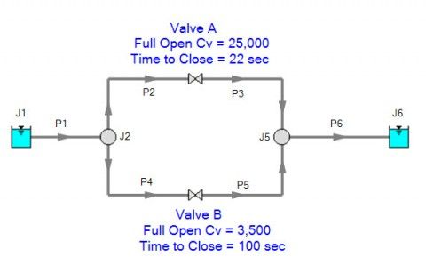

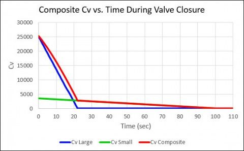
The closing profiles mentioned in Figure 1 are configured such that 80% of the composite Cv of the two valves in parallel will close in the first 20% of the total valve closure time (20 seconds in this case). The remaining Cv (20% of the composite Cv) will close in the last 80% of the time (or 80 seconds in this case). This is what we call the 80-20 effect, and a graph showing the Cv vs. time for the small and large Cv valves in parallel, as well as the composite Cv vs. time profile they combine to create, is shown in Figure 3.
This is compared to a constant closure for the valve shown in Figure 2 (remember, this is the valve with the total Cv equal to the steady-state, composite Cv of the two valves in parallel). Figure 4 shows this Cv. vs. Time profile for this single valve.
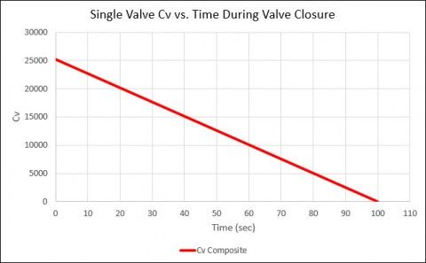
Notice that the Cv vs. time profiles in Figures 3 and 4 show the same total valve closure time (100 seconds), but the closure in Figure 3 decreases the Cv very quickly initially and then slowly completes its closure during the remainder of the time. The closure shown in Figure 4 is simply a linear-Cv closure. What benefit does the closure in Figure 3 provide over the closure in Figure 4? Let’s examine this in AFT Impulse.
The model in Figure 1 was run in AFT Impulse. Figure 5 shows the maximum and minimum pressures observed in the pipeline for both paths (one path through Valve A and the other through Valve B).
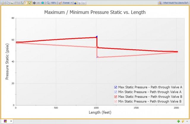
The maximum pressure observed in Figure 5 is roughly 63 psia, and the minimum pressure is about 44 psia.
Now let’s look at the maximum and minimum pressures that occur when the valve in Figure 2 with the linear valve closure is closed.
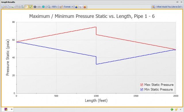
Notice in Figure 6 that the maximum pressure in this case is about 75 psia and the minimum pressure is just under 33 psia.
From Figures 5 and 6, it is evident that closing the two valves in parallel from Figure 1 in an 80-20 pattern can drastically reduce surge pressures compared to closing one valve with the same (composite) Cv linearly over the same amount of time. The difference between maximum pressures is about 12 psi, and the difference between minimum pressures is about 11 psi.
Using this 80-20 effect to close valves is an extremely effective approach to mitigating deleterious waterhammer because the second, smaller valve provides an outlet for pressure waves that occur as the large valve is closed, resulting in less pressure being trapped in the system. In the case of just one valve, pressure waves generated during the closure have less ability to escape and ultimately result in a higher pressure in the system.
Downstream of the closed valve, the more gradual decrease in flow translates to a smoother decrease in pressure. In several instances (although not this particular example), a fast valve closure can result not only in high surge pressures on the upstream end of the valve, but also problematic low pressures and resulting cavitation on the downstream end of the valve. Using valves in this parallel configuration to simulate the 80-20 effect can mitigate this highly undesirable consequence of a valve closure, as well.
Utilizing a parallel valve configuration like the one discussed in this blog during a valve closure will decrease maximum surge pressures and increase minimum surge pressures at the valve, compared to using a linearly closing valve with the same Cv in the same time period. By combining a large Cv, fast closing valve with a small Cv, slow closing valve in parallel, you can get the effect of a more complicated (and importantly, more expensive) valve that still closes relatively quickly while also mitigating the unwanted and frequently harmful effects of waterhammer.


Comments