


AFT Blog
Welcome to the Applied Flow Technology Blog where you will find the latest news and training on how to use AFT Fathom, AFT Arrow, AFT Impulse, AFT xStream and other AFT software products.
4 minutes reading time
(837 words)
Learn about the Acceleration Head and How to Model It
Ensuring your pump has sufficient net positive suction head available (NPSHA) is essential to reliable pump performance. For positive displacement pumps, this includes accounting for acceleration head, which will reduce a pump's NPSHA.
What is acceleration head? Acceleration head is the energy required to change the velocity of the liquid in the system from an at rest, or zero condition, to some non-zero value. From Newton's laws of physics, accelerating a mass (in this case a fluid) requires energy. Centrifugal pumps can see acceleration head during start-up as the fluid is accelerated, reflected by the peak power demand occurring during start-up which is higher than at steady-state. Positive displacement pumps however, unlike centrifugal pumps, constantly accelerate and decelerate fluid to generate pressure and flowrate.
Why should positive displacement pumps further consider acceleration head?
An analogy to demonstrate the energy requirements of acceleration head is the acceleration and deceleration of a car. A centrifugal pump operates like a car merging onto a highway. While the car requires energy to initially accelerate to highway speeds, the car only needs to add energy to overcome frictional losses to maintain that speed. Meanwhile, a positive displacement pump operates like a car in city traffic, constantly starting and stopping at traffic lights. In the city, not only does the car overcome frictional losses, but the car must also constantly add energy by burning gas as the car accelerates or remove energy as heat when the car brakes. The more frequent acceleration is why a car's city fuel economy is worse than highway economy. Like the car, a fluid in a pipe requires additional energy to constantly accelerate, captured as acceleration head.
The kinetic energy to accelerate the fluid is taken from pressure, reducing the pressure in the pipe and creating concern for cavitation.
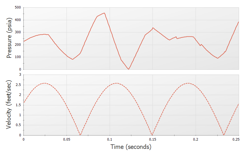
Figure 1: Demonstration of the dramatic change in pressure with change in velocity for a positive displacement pump, risking cavitation from low NPSHA at low pressures.
In positive displacement pumps, the energy to accelerate the fluid is returned on deceleration, so overall energy is conserved. However, in both centrifugal and positive displacement pumps, the rapid acceleration of fluid can cause cavitation concerns feeding into the pump as pressure decreases. Typically, centrifugal pumps only need to consider this when accelerating to their operating flowrate (like accelerating onto the highway), while positive displacement pumps should constantly consider acceleration head (like start-stop city traffic).
Calculating acceleration head
The magnitude of acceleration head depends on the mass being accelerated by the pump with each stroke. While fluid upstream and downstream of a positive displacement pump will be accelerated, acceleration head is typically calculated upstream of the pump due to NPSHA concerns.
Each suction pipe provides its own acceleration head which should be totaled. In more complex systems with multiple suction lines that combine before entering the pump, it can be impossible to calculate a single pump suction head. In calculation, it is essential to consider suction pipe dimensions, pump parameters, and fluid properties to accurately consider acceleration head, which we is further detailed in our documentation based on ANSI/HI 6.1-6.5-2015.
Figure 2 is a simple piping system driven by a positive displacement pump as built in AFT Fathom. While many parameters required by the standard to calculate acceleration head are already specified or calculated by the model (such as fluid density, pipe lengths, fluid velocity), other parameters must be specified by the user as seen in Figure 3 below.
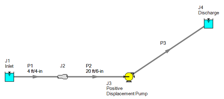
Figure 2: Example piping system provided by the ANSI/HI 6.1-6.5-2015 standard.
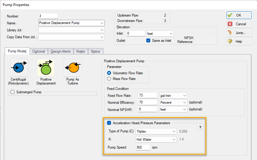
Figure 3: Specifications in the pump properties window required to calculate acceleration head from the ANSI/HI 6.1-6.5-2015 standard.
AFT Fathom will then calculate the acceleration head per pipe in accordance with the ANSI/HI 6.1-6.5-2015 standard, found in Figure 4. This example matches the US Customary specifications from the standard.
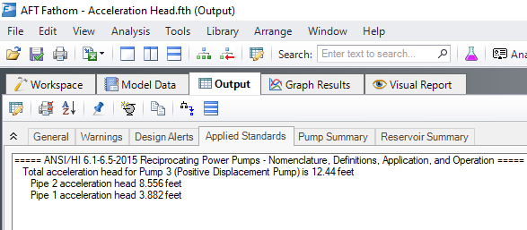
Figure 4: Acceleration head reported in the Applied Standards tab of Output.
Users can also add Total Acceleration Head to the pump summary tab from the Output Control, useful when comparing NPSHA and NPSHR.
Note that AFT applications do not subtract acceleration head from NPSHA automatically, and users must manually subtract Acceleration Head from the calculated NPSHA to comply with the standard.
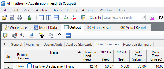
Figure 5: Acceleration head reported in the Pump Summary of Output.
Addressing acceleration head
Adding equipment can reduce this acceleration head by reducing the amount of fluid seeing the dramatic acceleration. Near a positive displacement pump inlet, adding a dampener provides a sink or source of flow depending on the stroke of the pump, smoothing the fluctuation in flow. Dampeners can similarly reduce pressure and flow fluctuations downstream to address vibration or pulsation concerns. This equipment should be sized properly, both volumetrically and considering pre-charge pressure, to ensure a dampener does not exacerbate pressure and flow fluctuation.
Comments