AFT Blog
Defining & Running 12 Scenarios in Less than 10 Minutes
A couple weeks ago, I wrote a blog article about the features, functionality, and how to use the Scenario Manager effectively in order to help the engineer save lots of time. In this article, I'm going to demonstrate a practical example of how it is possible to setup 12 different scenarios and run them in less than 10 minutes! The important thing to pick up from this practical example is the thought process on how to setup the scenario tree in the most effective and efficient manner possible.
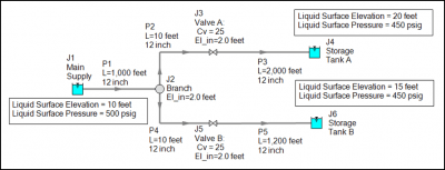
Consider the system below in Figure 1 where three liquid hydrocarbons at cryogenic conditions including methane, ethane, and propane need to be delivered to two separate storage tanks. The system will only supply one tank at a time. All piping is stainless steel - ANSI material, 12 inch diameter, schedule 40S. The liquid hydrocarbon temperature is -150 deg. F and all pipes are assumed to be perfectly insulated and thus the heat transfer mode is adiabatic. It is necessary to determine the liquid hydrocarbon delivery flow rate to each storage tank.
Figure 1 - Liquid hydrocarbon delivery system for methane, ethane, and propane at cryogenic conditions. System will supply only one tank at a time.
The first step would be to build the model and define all the pipes and junctions, which can be done very quickly in this system with the global editing feature. A default fluid can also be defined such as liquid methane.
After the system has been built, it is time to start thinking about the different scenarios that need to be modeled and analyzed. First, create the new scenarios, then modify each scenario accordingly.
For this system, there needs to be three separate fluid cases modeled because the system will only supply one fluid at a time. Therefore, three separate scenarios for a "methane case", "ethane case", and "propane case" can be created. Within each fluid case, there are two sub-cases where the fluid is first supplied to Storage Tank A, and then a second sub-case where the fluid is supplied to Storage Tank B. All in all, there are a total of six individual cases that needs to be ran and analyzed (i.e., 3 fluid cases x 2 separate delivery cases).
You could create each scenario individually and then define it according to its particular case. However, there is a much more effective way to setup all six cases for this system.
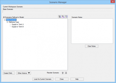
The Base Scenario has already been created and uses methane as a base fluid. To develop a Scenario Manager tree that makes sense, the first case to be created would be a new child case called "Methane Case". This scenario is created as an identical copy of the Base Scenario and since Methane is already defined, nothing needs to change. Next, two child cases of the "Methane Case" can be created and given names such as "Supply to Tank A" and "Supply to Tank B", as shown in Figure 2 below.
Figure 2 - Methane Case with two child cases to supply methane to Tank A & then to Tank B.
Now, load each tank supply scenario individually, and then close the valve that fluid is NOT being supplied to in that scenario. This sets up the appropriate delivery conditions for each case.
At this point, select and load the "Methane Case" scenario. Then in the Scenario Manager, with the "Methane Case" scenario selected, right-click and choose "Clone with Children". This duplicates the whole "Methane Case" scenario tree.
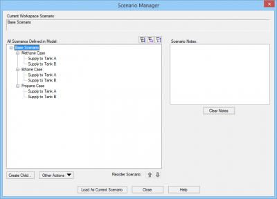
Select the new "Methane Case (2)" scenairo and rename it as "Ethane Case". Then clone the "Ethane Case" with its children and rename the "Ethane Case (2)" scenario to be "Propane Case". The final scenario tree will appear as shown in Figure 3.
Figure 3 - All six delivery cases created effectively with the "Clone with Children" option. Each supply scenario loaded individually and the valve that does not receive fluid is closed.
After that is completed, load the "Ethane Case" and "Propane Case" individually, and change the fluid appropriately for each of those scenarios. This fluid change in each parent scenario will propagate to each individual child delivery case.
Now, run all six cases using the Batch Run feature from the File menu and determine the flow rate to each Storage Tank. The resulting flow rates are shown in Figure 4 below.
Figure 4 - Resulting delivery flow rates to each storage tank with 12 inch piping.
As you can see, it takes very little effort and a short period of time to setup each case that needs to be modeled efficiently and effectively with the various Scenario Manager features such as create child, clone, and rename.
Let's take this one step further...Your boss comes back and mentions that they'd like to see what flow rates can be achieved by using 16 inch piping for all six scenarios. This is very easy to accomplish and only takes about 1 - 2 minutes of your time to generate the additional results.
Since the Base Scenario was created with 12 inch diameter pipes, it would be really nice to clone the Base Scenario with all its children. However, it is not actually possible to clone a base scenario since it is meant to be the base scenario in which all child scenarios are created from. This is where the "Insert Scenario Above Selected" option is very useful!
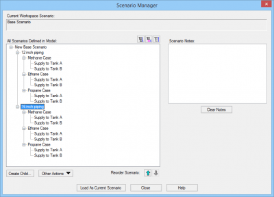
In the Scenario Manager, select the Base Scenario, then right-click (or choose from the Other Actions drop-down menu) and choose "Insert Scenario Above Selected". Give the new base scenario a name such as "New Base Scenario". Then, consider renaming the original base scenario when prompted to something such as "12 inch piping". Now, you can select the "12 inch piping" scenario, and choose "Clone with Children". Rename the cloned scenario to "16 inch piping" as shown below in Figure 5.
Figure 5 - New scenario tree including 16 inch piping for the same six delivery cases.
At this point, load the new "16 inch piping" scenario. The ONLY change that needs to be made is to globally edit the pipes to be 16 inches in diameter AND THAT'S IT!!! Then, simply switch out the 12 inch cases with the 16 inch cases for the Batch Run and then examine the new results shown in Figure 6.
Figure 6 - Results for 16 inch piping delivery cases.
Comparing the 12 inch results to the 16 inch results, it is very easy to see that the larger diameter pipes do not allow any more flow based upon the system supply and discharge conditions. Therefore, it only took 1 - 2 minutes to save thousands of dollars that would have been spent on larger pipes that would not add much value.
Overall, I hope that this article helps improve understanding on how to use the Scenario Manager more effectively and how it truly does have the power and capability to save you enormous amounts of time so you can be more efficient with your work.


Comments