


AFT Blog
Welcome to the Applied Flow Technology Blog where you will find the latest news and training on how to use AFT Fathom, AFT Arrow, AFT Impulse, AFT xStream and other AFT software products.
Often times when building larger network models, you may not be sure what the direction of the flow will be and running the model is the only way to determine the flow direction. In the below AFT Arrow model it might be hard to determine what way the flow convention is in some of the loops. After running this model there are cautions stating that flow is negative through junctions that may have loss factors that are dependent upon direction. What is the easiest way to fix this? You could compare your results, remember or make a table of what pipes...
7315 Hits
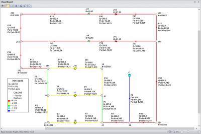
Each AFT software product employs five Primary Window tabs in which you would build, define, and analyze the model of your system. Of these, the Visual Report window is incredibly useful in that you are able to overlay your model input or output parameters directly on top of the graphical layout of the system itself. This is an excellent feature to use when you want to provide the bottom line results to clients and colleagues at a high level (or a detailed level). Figure 1 is an example of what the Visual Report for a particular system might look like. As...
7806 Hits
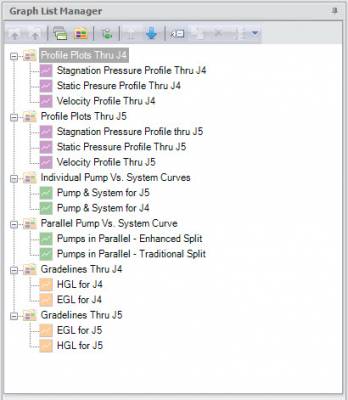
AFT software products have had powerful graphing capabilities for a very long time. Many types of graphs can be created with AFT products such as pump vs. system curves, profile plots along a flow path, gradelines and elevation profiles, transient plots (with AFT Impulse or the AFT Fathom XTS module), slurry system curves (with AFT Fathom SSL or AFT Impulse SSL modules), and selected solutions that allow you to plot various output parameters for desired pipes. All of these graphing capabilities are incredibly important to engineers as they analyze the hydraulic behavior of their system. The ability to customize the graphs...
5085 Hits
One of the newest features of AFT Fathom 9 that will add a lot more efficiency to analyzing your results is the new Design Alert Manager! In addition to the new Design Alert Manager, it is also possible to add general Design Alerts for junctions such as inlet or outlet pressure, or perhaps the pressure loss across a junction. In previous versions of our software, it would be possible to create different Design Alerts for pipes where you could specify a minimum or maximum value for a particular output parameter such as a maximum pressure limit, minimum flow rate, maximum velocity,...
5297 Hits
Mismatched fluid handling machinery and the systems they service are a frequent occurrence in industrial, municipal and commercial fluid transfer installations. And, as I found out this morning, in residential installations. Specifically, in the residential installation in which I personally live.
5482 Hits
Well, if the answer is "more than one", then you are probably struggling to deal with way more model files than you need to be. With all AFT products, the Scenario Manager is an incredibly powerful feature that allows one to model several different cases within a single model file. This includes different operating conditions, multiple pump configurations, different piping, system expansions, hot days, cold days, insulation, fouling and pipe scaling, etc. The list of different cases that can be modeled is essentially endless! So, I have said it once, and I will say it again...The Scenario Manager is one of...
9557 Hits
I like cool new features in software. And I am especially proud of those in the upcoming AFT Fathom 9. We expect this new version to be available in the next two months. Below I will touch on some of the new features I think will be of most interest to you.
4482 Hits