AFT Blog
Making the AFT Workspace Your Own: Workspace Customization Options and Modeling Tips that Visually Enhance Your Hydraulic Model
Engineers using AFT hydraulic software (Fathom, Arrow, and Impulse) know that they are utilizing powerful flow modeling tools capable of modeling real fluid behavior in simple and complex piping networks, but many are often unaware that our software also provides a vast array of customization options that can visually aid the user’s understanding of the physical layout of the modeled system and help highlight important model components. Even though these visual options do not affect the hydraulic calculations, they can greatly improve modeling efficiency and overall model comprehension, especially if the model is shared between engineers or contains several pipes and junctions.
The following list details Workspace customization options you can use to visually enhance your model. Note that most of these options are accessed using the User Options window located under the Tools menu, or through the Optional tab on the individual pipe or junction Properties window:
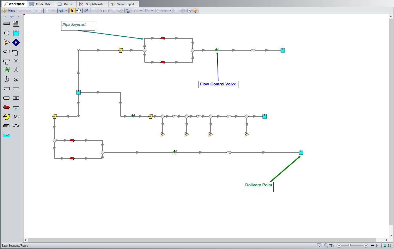
1.) Segment pipes (see Figure 1)- We frequently receive models in our support center that contain an unnecessary amount of pipes and/or junctions because the user was unaware of how to segment pipes. Segmenting pipes divides the pipe into segments to allow you to bend the pipe and maneuver it around the model Workspace without having to add a branch junction (and therefore, an additional pipe) each time you want to visually bend a pipe. Note that these segments, as all visual options described in this blog, are purely for visual enhancement and do not affect hydraulic calculations. To add or remove a segment from a pipe, select the pipe by clicking on it, then either click on the Add/Remove Segment icon or go to the Arrange menu on the toolbar, click Pipe Segments, then specify how you want to segment (or de-segment) your pipe.
2.) Add annotations (see Figure 1)- You can choose to add annotation boxes that allow you to include written information on the Workspace. The font, size, and color of the text in the annotation can be customized, as can the annotation shape, background color, and border. You can also select to add a line that points to specific model components, as well as anchor the annotation to these components or to the Workspace itself.

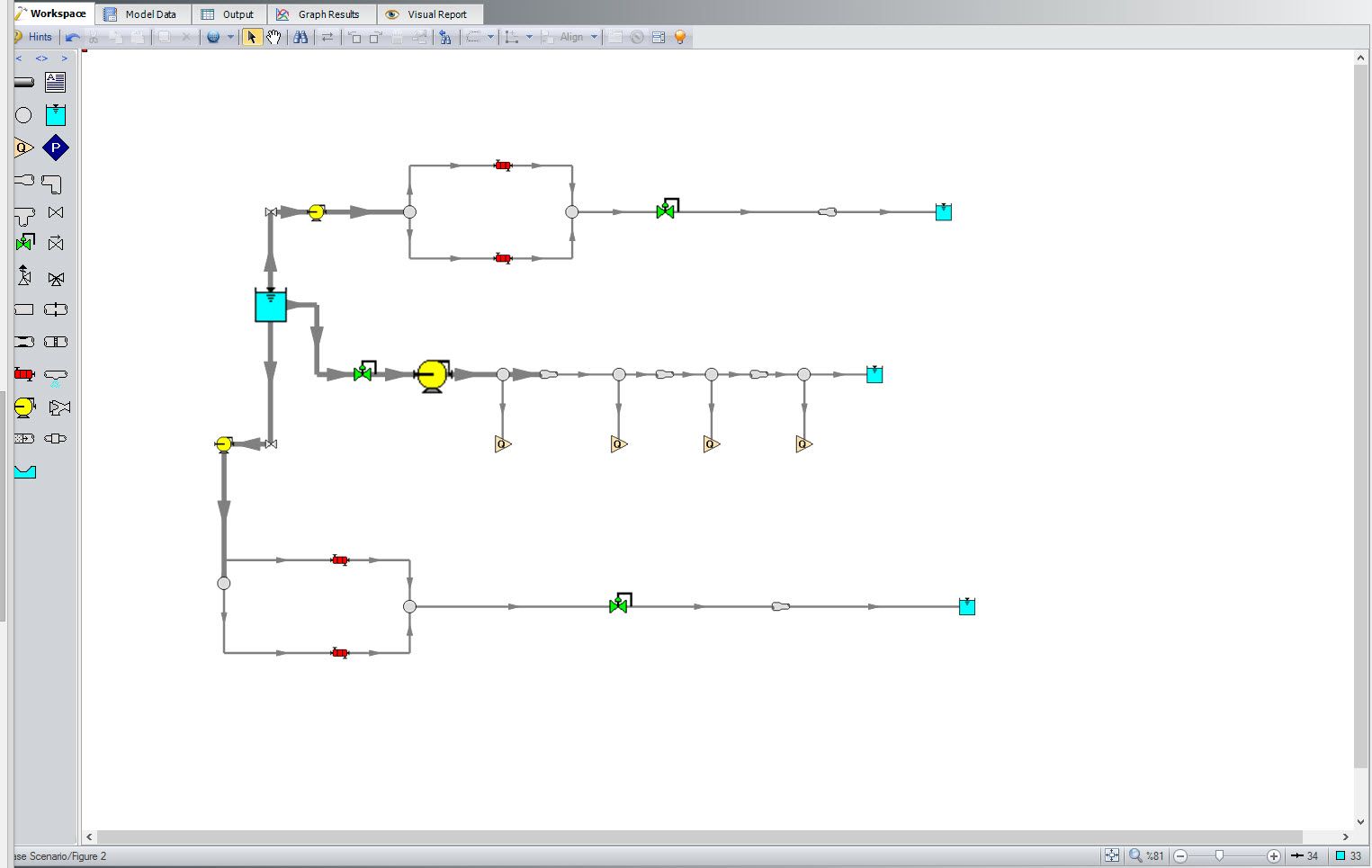
3.) Change the pipe thickness on the Workspace (see Figure 2)- You can change the appearance of the pipe thickness on the Workspace in one of three ways from the User Options Window under Workspace > Pipes:
a.) Universally show all pipes with the same thickness
b.) Vary pipe thickness on a gradient based on pipe diameter
c.) Vary pipe thickness on a gradient based on a range of pipe diameters (pipe diameters falling below this range will have the minimum specified thickness, while pipe diameters above this range will have the maximum specified thickness)
Alternatively, the pipe diameter thickness on the Workspace can be adjusted pipe-by-pipe through the Optional tab on each pipe’s Properties window.
4.) Change junction size (see Figure 2)- You can make a junction appear larger or smaller than its default size. This feature is helpful for a variety of reasons that range from visually representing expected junction flow capacity to emphasizing junctions of interest (for example, a fixed-flow pump being used to size a future pump). Changing the junction size is performed from the junction’s Optional tab in its Properties window. From this tab, uncheck the box next to Use Workspace Default for Size and select the custom icon size for the junction to be displayed.
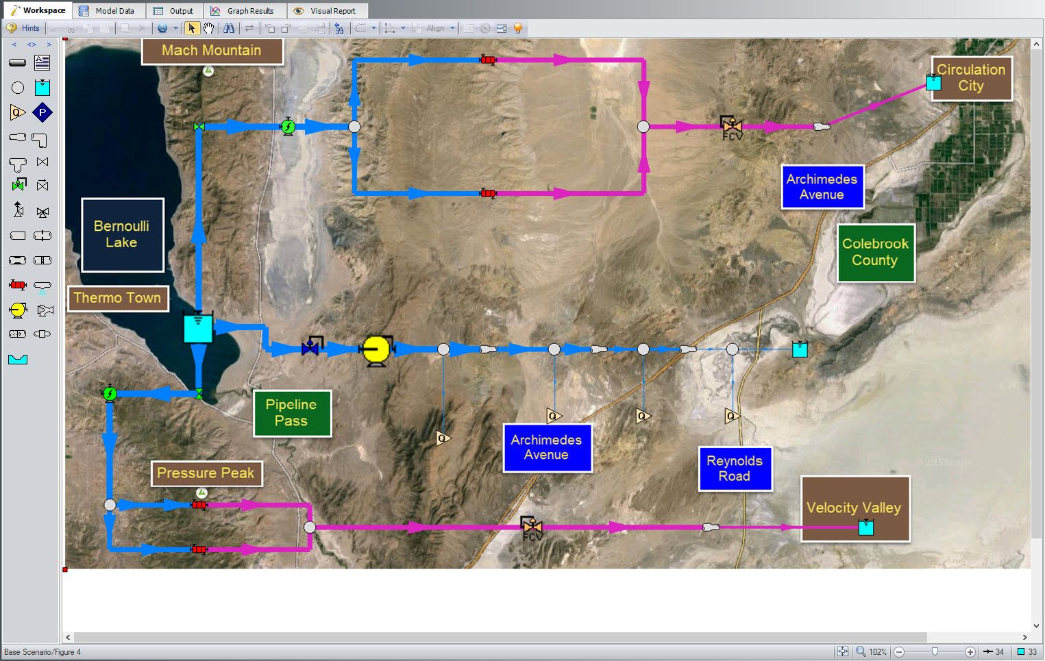
5.) Change icon type of same junction type (see Figure 3)- You can choose from a variety of icon styles for a given junction. This feature is especially helpful in differentiating various types of the same equipment (such as flow control valves and pressure reducing control valves). This option is specified in the individual junction’s Properties window under the Optional tab below Workspace Icon > Change Icon.
6.) Change pipes and/or junction colors (see Figure 3)- You can change the color of pipes and junctions displayed on the Workspace to demonstrate important differences in these model components that would otherwise be non-obvious from simply looking at the Workspace. Customers frequently use this option to indicate the flow of fluids of different densities or temperatures through these pipes and junctions, pipes made of different materials (steel vs. copper tubing), or pipes and junctions located in different regions of the system.
Additionally, this option allows the user to indicate a difference in otherwise similarly appearing junctions such as using one color for a pressure control valve and another for a flow control valve. The pipe and junction colors are modified in each component's Properties window under the Optional tab.
7.) Import a background image (see Figure 4)- You can import any image onto the Workspace background. This feature is very helpful in serving as a reference for laying out the model components. Users will frequently import an image of a map and place their pipes and junctions in reference to the map to illustrate the location of system equipment.
The expansiveness of Workspace customization options and visual tools in AFT software can greatly aid the user in his/her hydraulic modeling by providing the flexibility to visually represent the system in a way that improves comprehension of system configuration. Therefore, we highly encourage you to familiarize yourself with these Workspace customization options and tools to make the AFT Workspace your own!


Comments