AFT Blog
Behold The New and Improved Design Alert Manager
AFT introduced the Design Alert Manager in 2015 and it has proven to be a highly valuable tool to better organize Design Alerts within AFT model files. With the 2023 releases of all AFT products, the Design Alert Manager has been reorganized to improve the process of creating and applying user-defined alerts. It is now much easier to create, edit, and organize Design Alerts for a more transparent experience.
The Design Alert Manager is a powerful tool used to set up customized alerts to notify users of important output parameters. Design Alerts can be configured for different parameters and applied individually to certain pipes or junctions. These alerts allow users to quickly review model output for any undesirable conditions in their systems. They do not affect the results or operation of the model. You can set alerts for pumps exceeding certain speeds, pipes experiencing vacuum pressures, and much, much more!
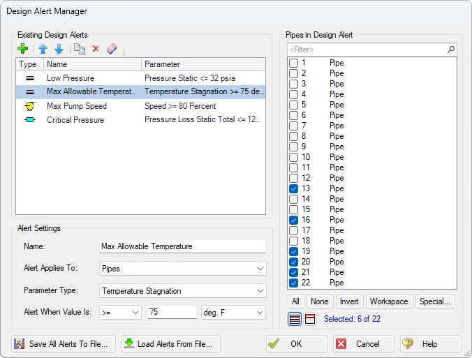
The Design Alert Manager can be accessed from the Tools drop down menu or from within a pipe or junctions' property window. Within the Design Alert Manager, there are three distinct sections: the Existing Alerts section, the Alert Settings section, and the Objects in Design Alert section.
In the Existing Alerts section (Figure 1), you can create, reorder, duplicate, and delete Design Alerts. Existing Design Alerts will appear here with their type, name, and parameter displayed. This way, you can easily locate and organize your Design Alerts.
Below this section, you'll find the Alert Settings. This is where you can set the alert parameters. An assortment of different parameters are available to choose from, including junction-specific parameters.
On the right, you can select which pipes or junctions the alert is being applied to. You can quickly select the pipes or junctions from this section, and you can use the available selection tools at the bottom to better sort and select the appropriate objects as needed.
With the newly reorganized Design Alert Manager, creating your own Design Alerts is a much more streamlined and simple process. To create a Design Alert, follow these easy steps:
- Select the green plus icon to create a Design Alert
- Give it a descriptive name
- Define the object (pipe or junction) that the alert applies to
- Define the parameter type to evaluate (e.g., pressure and flow rate)
- Enter the condition and value that would trigger the alert
- Maximum and minimum conditions
- Units can be customized
- Select the objects from the Workspace that the Design Alert will apply to on the right
It's important to note that Design Alerts are defined globally but applied to specific scenarios. This means that different scenarios can have different applied Design Alerts, allowing better analysis of different scenarios and system conditions. Applied Design Alerts will still follow ordinary scenario inheritance rules, meaning child scenarios will have the same applied Design Alerts as parent scenarios until changed by the user.
You can also save and import Design Alerts to other model files. This can save you time when you have multiple projects with consistent standards, so you won't need to redefine your Design Alerts in each model file (Figure 2).
Similar to previous versions of the software, Design Alerts are still shown from within the pipe or junction property window and can also be toggled from there, as well as providing quick access to the Design Alert Manager.
After defining and applying Design Alerts, the Output window will show which Design Alerts have been exceeded. The Design Alerts tab lists and organizes all triggered Design Alerts and the parameters that the alerts correspond to will be highlighted in the Output as shown in Figure 3.

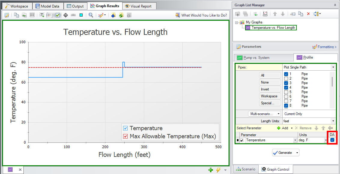
The Design Alerts can also be cross plotted against the same output parameter for various profile plots. When creating a profile graph, select the "DA" checkbox indicating that Design Alerts will be displayed on the graph. You can customize the formatting of the graph to adjust the line style and colors to create easily readable graphs visualizing whether your system is exceeding your Design Alerts.
The Design Alert Manager can be used in a number of applications to help users check whether their systems are following applicable standards, properly working within desired operating conditions, and monitor any other important factors within a piping system.
There is a lot of customizability within the Design Alert Manager that can help to improve an engineer's efficiency when analyzing their piping systems.
Comments