AFT Blog
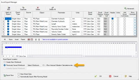
The Opposite of Good Vibrations - Evaluating FIV, AIV, FIP Guidelines from AFT Fathom and AFT Arrow
Learn how to use AFT Fathom and AFT Arrow to help calculate the Likelihood of Failure (LOF) for Flow Induced Vibration (FIV), Acoustic Induced Vibration (AIV), and Flow Induced Pulsation (FIP) in accordance with Energy Institute Guidelines to avoid v...
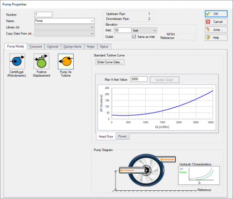
It's a Pump! It's a Turbine! It's a Pump as Turbine!
Pumps and turbines may serve opposite purposes, but fundamentally, they operate under the same principles. Both pieces of equipment convert between usable work and fluid energy, and both often use an impeller to make the conversion. Differences betwe...
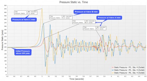
What Is Transient Analysis?
You're tasked to perform a transient analysis of a piping system and it would be really helpful if there was a good software tool out there to help you. Well, you've come to the right place because AFT has great solutions! ...

Know Your Pump & System Curves - Part 3
In the final "Know Your Pump & System Curves" blog series, I am going to discuss the complexities behind pump vs. system curves for systems with pumps in series and parallel configurations. Multiple pumps in series configurations are relatively s...
Digital Twin – Identical or Fraternal?
When I was a child, I was jealous of twins. I thought how cool it would be to have a twin. I had twin cousins a few years older than I was that I saw on a frequent basis. I always got them confused. Which one was Roger, and which one was Ronny? A buz...

That Valve’s Got Character – Applying Pre-defined Characteristic Curves
Valves are often oversimplified during modeling. Understandably, defining a valve with its range of Cv at various open percentages requires much more information than an engineer may have during the initial design phase. However, just like handbook d...
Classically, hydraulic loss tends to be categorized as major losses, which are due to friction between the fluid and the pipe's inner surface, and minor losses, which are due to entrances, exits, fittings, and other component effects. Losses due to friction tend to have a greater impact on the hydraulic resistance and this could be the main reason ...
AFT introduced the Design Alert Manager in 2015 and it has proven to be a highly valuable tool to better organize Design Alerts within AFT model files. With the 2023 releases of all AFT products, the Design Alert Manager has been reorganized to improve the process of creating and applying user-defined alerts. It is now much...
Much can be done to reduce model run times, but it's a fact of life with transient simulations that some systems are just large and complex, need to cover longer spans of time, or have dynamics that can only be accurately captured with finer sectioning. In such cases, long run times can be unavoidable. Have you ever needed to pause a lengthy s...
The Annotation Tool has new shapes and customization options which will help you organize, markup, comment, and effectively present your models when using the new versions of Fathom 13, Arrow 10, Impulse 10, and xStream 3. In addition to the pre-existing rectangles and ellipses, you can now add diamonds, pentagons, hexagons, octagons, clouds, trian...
A year ago, a fast-rising crypto trading company, FTX, with a splashy office in the Bahamas, failed spectacularly. I just finished reading an intriguing book called Going Infinite: The Rise and Fall of a New Tycoon by the always intriguing author, Michael Lewis. The book takes a deep dive into FTX and its founder, Sam Bankman-Fried. Some of ...
The release of AFT xStream 3 brings with it reciprocating compressors for your gas transient models! Positive displacement compressors now have two subtypes: fixed flow rate for a steady mass or volumetric flow rate, as was present previously, and the all-new reciprocating compressor option. The reciprocating compressor model is for compressors in ...
A Compressor Map in AFT Arrow allows you to more accurately model the full range of operating conditions for a Centrifugal Compressor junction. AFT recognized the need for this specific feature from customers via support requests and consulting projects. Well, good news…this capability is here! The featu...