Pumps and turbines may serve opposite purposes, but fundamentally, they operate under the same principles. Both pieces of equipment convert between usable work and fluid energy, and both often use an impeller to make the conversion.
Differences between the two pieces of equipment quickly start to appear as they are examined with more detail. A pump impeller spins at high speed to add energy to the fluid - first as kinetic energy and later converted to pressure energy. A turbine impeller uses a high-velocity fluid stream (or a large pressure differential in a fluid) to spin at high speed and remove energy from the fluid.
The impeller in each piece of equipment is meant for a slightly different task, and is often highly specialized for that task. However, a pump impeller can still be used as a turbine, and vice versa.
When is a Pump used as a Turbine?
Many applications exist where the working fluid is both pumped to high pressure (or elevation) and returned to low pressure (or elevation). Pumping to high pressure requires a large energy consumption even as returning to low pressure creates a situation for useable energy generation.
An engineer designing a system for these applications must decide whether to recover the useable energy while returning to fluid to a low energy state. Ideally, they would design the system to recover that energy. However, the real world has many additional considerations.
The cost savings in a system with a large amount of recoverable, useable energy are often large enough that dedicated, highly efficient turbines make sense. Dams and hydroelectric power plants are examples of these systems. The cost savings in a system with a small amount of recoverable, useable energy may not outweigh the costs of installing equipment to recover that energy.
Somewhere in between are systems with moderate amounts of recoverable energy. The cost savings may be significant, but it may not be large enough to justify installing and maintaining a dedicated turbine. In these systems, it may be more cost effective to let the pump run in reverse to capture that energy. The pump run in reverse as a turbine will be less efficient than a dedicated turbine (typically a 5% reduction in efficiency or less), but it avoids buying an expensive turbine.
Small-scale pumped hydroelectric storage systems are a common example of a system where running a pump as a turbine makes sense. The benefit of pumping water to a higher reservoir for later electricity generation is present, but the cost of a dedicated turbine might outweigh that benefit - especially given that the pump and the turbine don't need to be used simultaneously.
Defining Pumps as Turbines in Fathom and Impulse
Both AFT Fathom and AFT Impulse give users the ability to model a Pump as Turbine (PAT) using the Pump junction.
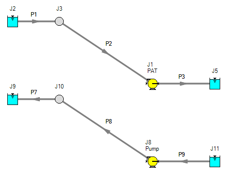
Note that the Centrifugal Pump and the PAT options are both available in the Pump junction, but are defined with opposite sign conventions. The Centrifugal Pump defines a positive dH as a head rise, while the PAT defines a positive dH as a head loss. The Centrifugal Pump defines positive flow direction as the direction flow is being pumped, while the PAT expects the positive flow direction defined as the direction flow is moving while the pump is used as a turbine. Figure 1 below compares the same system set up to model flow through a PAT vs flow through a Centrifugal Pump.
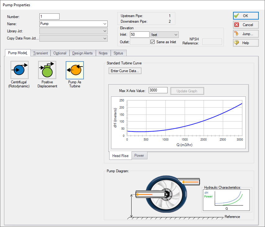
Modeling a PAT requires many of the same inputs as the standard Centrifugal Pump option. The key piece of data required to model a PAT in either Fathom or Impulse is the Turbine Curve. This curve describes the head/pressure loss across the junction as a function of flow rate. It also describes the power produced by the pump as a function of flow rate. Figure 2 below shows an example Turbine Curve defined in Fathom.
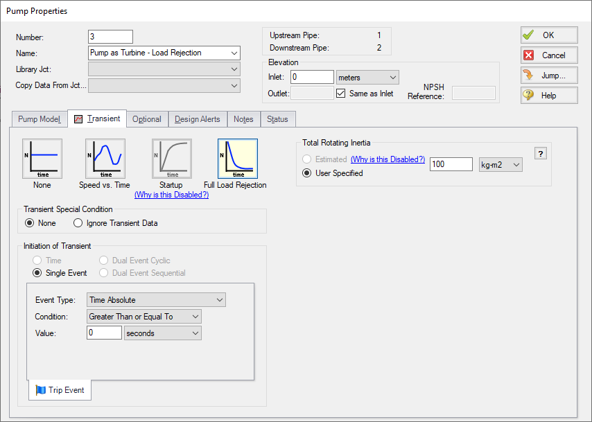
Other expected inputs are Rated Speed and Total Rotating Inertia for the PAT. Figure 3 below shows an example turbine transient with the Total Rotating Inertia defined in Impulse.
How does the PAT Work?
Normal operation of a PAT is dictated by where the turbine curve and system curve intersect, similar to how a pump will operate where the pump curve and system curves intersect. The system has some driving force for flow (either pressure differential or elevation change), while the PAT has some resistance to flow. These two factors dictate where the PAT will operate. Fathom and Impulse will then use the Power curve for the PAT to report how much power will be generated at that flow rate.
Another common mode of PAT operation is when the PAT is decoupled. Decoupled operation means the PAT impeller is not connected to the motor, is spinning freely in the fluid stream, and is not generating energy. When the PAT is decoupled, it operates at the No Load point (the flow rate where power generation is zero, seen in Figure 4 below. The No Load point changes depending on the speed at which the impeller is spinning. Both Fathom and Impulse can model decoupled PAT operation as system operation changes.
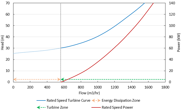
Impulse will also model the PAT moving from normal operation to decoupled operation during a process called load rejection. During the load rejection process, the PAT impeller will increase in speed as the PAT moves from the turbine curve to the No Load point.
AFT's documentation includes a more detailed discussion on how the PAT works in both AFT Fathom and AFT Impulse