If you have a system where there are several area changes throughout the piping, modeling every single area change and connecting pipe can become taxing and time consuming. Also, the more pipes and junctions that are in a model, the higher the complexity.
With AFT software, it is very simple to include the area change losses in the pipes themselves!
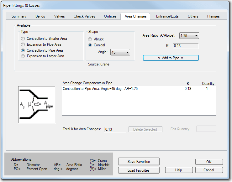
As seen in the Pipe Fittings and Losses screen shot below, there are four area change types that can be used and either abrupt or conical shapes can be modeled. The key to determining which expansion or contraction type to use depends on the location of the area change in the pipe that is being modeled and the associated area ratio.
The area change loss models in AFT Fathom were taken from Crane 1988 and all K factor relationships for area changes require an area ratio.
With modeling a physical area change junction, the area ratio is automatically determined by the size of the upstream and downstream pipes, and you can choose whether to use either the upstream, downstream or a different diameter for the basis of your area ratio.
When including the area change as an additional fitting to a pipe, you need to determine the area ratio to use ahead of time. For all contractions and expansions, the area ratio (AR) is always defined by the following relationship.
The basis area for the calculation (Apipe) is taken from the Pipe Model tab in the properties window and it is worth noting that Apipe is not arbitrary. If "A" is assumed to be a larger pipe being contracted down to the specified pipe diameter "Apipe", then the ratio will be greater than 1. However, if "A" is assumed to be smaller than the specified pipe area, then the area ratio will be less than 1. This is best illustrated by way of example.
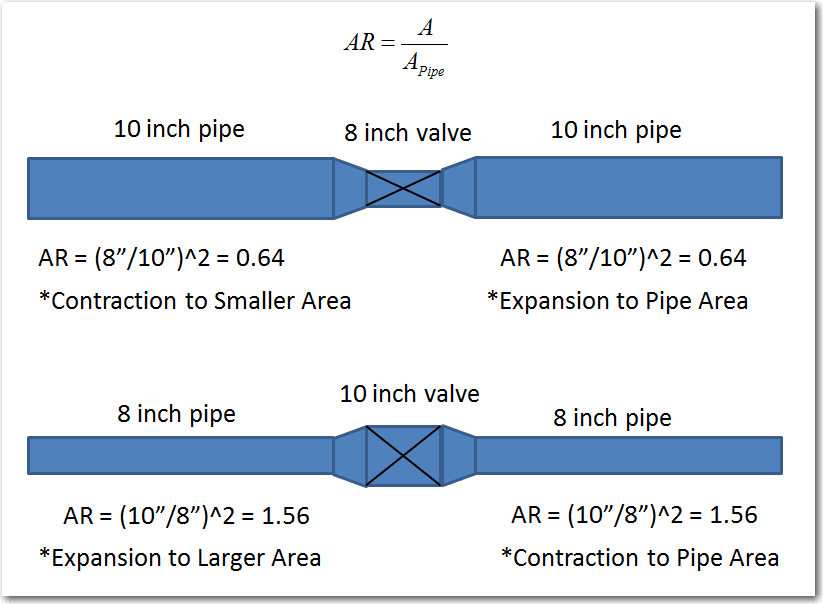
The picture below illustrates two potential cases that can be modeled where the main piping diameter is different than the diameter of a valve.
As you can see, the area ratios for the upstream and downstream pipes are the same in either case.
With the direction of flow going from left to right in both cases, the top case is a contraction – expansion while the bottom case is an expansion – contraction. The upstream pipes in both cases use a “smaller” or “larger” area change type and the downstream pipes use the “pipe” area change type.
All in all, this method is useful because in either case, two extra junctions do not have to be modeled. Also, if there was a short length of piping between the area changes and the valves, the short piping may not need to be modeled either, if you decide you want to neglect the short pipe. Thus, the equivalent losses due to the area change are still maintained in the model without the extra complexity!


