Using “Specified Heat Rate In Constants” for the thermal model of heat exchangers can often cause problems in system models. The reason why is because this thermal model type causes the heat exchanger to act like an “assigned heat input” junction as does an assigned flow junction does for providing constant flow rates. Another problem is that this thermal model can cause unrealistic temperature changes across a heat exchanger. When the heat rate is specified and the mass flow rate and heat capacity are calculated based on the system solution, the temperature change will be whatever is required to maintain the specified heat rate. This is analogous to the way an assigned flow junction will add whatever pressure is necessary to maintain a specified flow.
It is always best to use other heat exchanger thermal models and the heat rate for the heat exchanger will be available as an output that can be compared against the original desired heat rate.
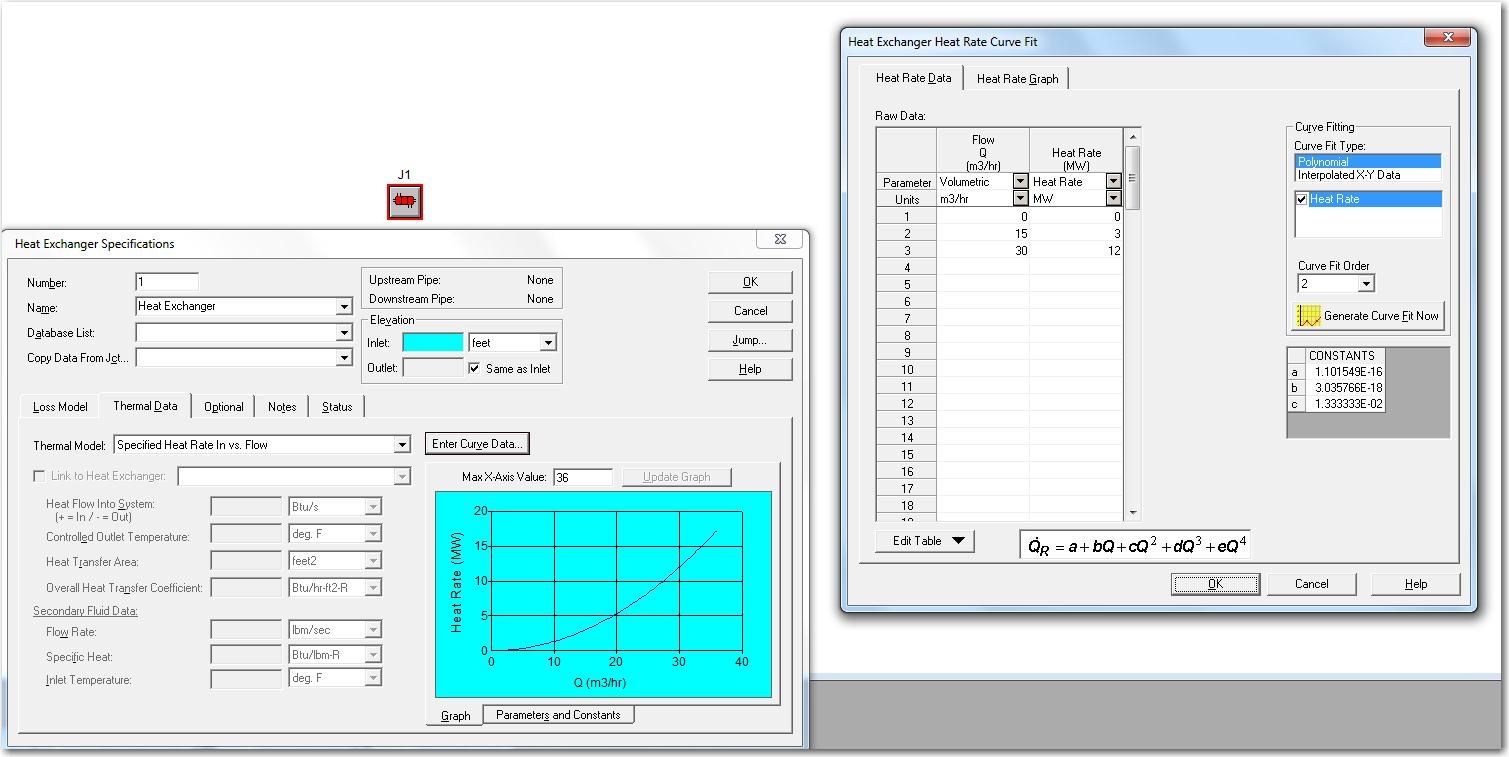
If the heat rate is known as well as a function of flow rate, then the thermal model “specified heat rate in vs. flow” can be used. One would enter this information into a table just like establishing a resistance curve as a pressure loss model. Use the zero point as the first data point (zero flow rate and zero heat input). Then enter the heat rate and mass flow rate that is known, and finally add one more data point where the flow rate is doubled and the heat rate is quadrupled. This will allow the heat exchanger to modulate its heat rate with the system flow rate and can produce more accurate results. The screenshot below contains the data needed for the curve fit as well as the generated curve in the heat exchanger specifications window itself.