For gas systems flow is driven either by a pressure difference, or by a turbomachine. AFT Arrow allows users to model turbomachines such as fans, blowers and compressors. For this blog we'll talk about what differentiates these three options, and how to model them using AFT Arrow.
Definitions and Types
Fans, blowers and compressors all serve the purpose of moving gas from one place to another. The distinction between these machines is the discharge pressure to suction pressure ratio (specific ratio) that each machine can achieve. ASME defines the specific ratio range of fans as 1 to 1.1, blowers as 1.1 to 1.2 and compressors as 1.2 and greater.
Fans, blowers and compressors can each be categorized by two types, centrifugal and positive displacement. Centrifugal turbomachines are dependent on the system pressures to determine the operating flow rate. Manufacturers will provide a performance curve, generally in terms of pressure and standard volumetric flowrate, which can be used to determine the flow rate based on the pressure at the centrifugal compressor/blower/fan. Positive displacement turbomachines have essentially vertical performance curves - they will operate at a constant flow rate, though the pressure rise will vary.
It is interesting to note that the term "positive displacement fan" is rarely used in industry. This is because typically positive displacement machines exceed the specific ratio of 1.1, and would thus be categorized as blowers or compressors.
Compressor/Fan Models in Arrow
In AFT Arrow the Compressor/Fan junction can be used to model all three of the turbomachines described above. On the compressor model tab three models are available: Centrifugal Compressor, Fan, and Positive Displacement Compressor.
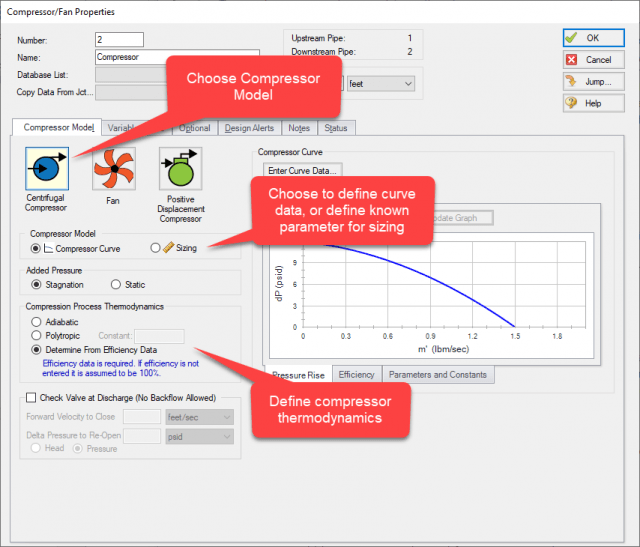
- Centrifugal Compressor: This option can be used to model an actual centrifugal compressor by entering a compressor curve or may be used to size a centrifugal compressor by selecting the "sizing" option and entering a known sizing parameter. The thermodynamic behavior of the compressor may be specified, and a check valve may be added to prevent reverse flow through the compressor. A centrifugal blower may also be modeled using this option. (Figure 1)
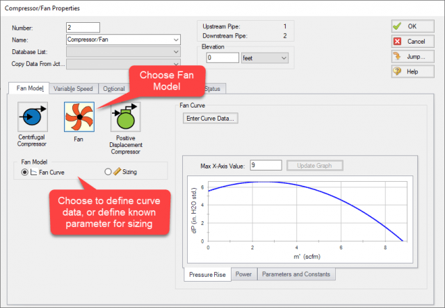
- Fan: This option can be used to model a centrifugal fan, and can in some cases model a centrifugal or positive displacement blower if the temperature rise is low as discussed below. A positive displacement blower with a fixed flow would be represented using the "Sizing" option. (Figure 2)
- Positive Displacement Compressor: This option can be used to model a positive displacement compressor or blower using a fixed flow rate.
Thermodynamics for Compressors/Fans
You probably noticed that the fan model does not provide the option to define the compression process thermodynamics. All fans in Arrow are treated as adiabatic and 100% efficient (isentropic). This is because fans operate at such low pressures that the temperature change is practically negligible across the fan.
To model a non-ideal turbomachine, such as by entering a polytropic constant or with an efficiency curve, then one of the compressor models should be used instead of the fan option.
Modeling Multiple Speeds
To model a turbomachine in Arrow that operates at different speeds for different cases, care should be taken with how to represent this.
The Variable Speed tab can be used to represent how fans and blowers operate at different speeds using the affinity laws. Note that the affinity laws are only valid for gas flows which remain below a Mach number of 0.3 at all points within the turbo machine [1]. This means that variable speed compressors should not be represented using the variable speed option. To model compressors operating at less than 100% speed, consider using the Multiple Configurations option to enter compressor curve data from the manufacturer to represent different speeds, as described below.
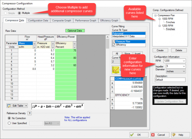
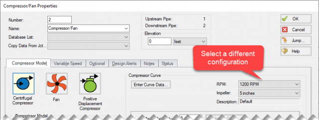
The Multiple Configurations option can be used to directly enter compressor curves for various compressor speeds as shown in Figure 3. This allows the user to enter multiple compressor curves, which can then be selected from the list of defined curves to switch between them. Note that Arrow will not automatically switch between the curves during the run, such as can be done using the controlled option on the variable speed tab. However, this option makes manually switching between curves simple by allowing different configurations to be selected quickly on the Compressor Model tab (Figure 4).
In general, the main difference between fans, blowers and compressors will simply be the difference in the specific ratio for each. Since fans have a smaller pressure and temperature change across them input can be greatly simplified using the Fan model, while blowers and compressors will often require some additional input to model accurately. See the AFT Arrow help file for more information.
References
[1] Casey, M., and Robinson, C. (November 8, 2012). "A Method to Estimate the Performance Map of a Centrifugal Compressor Stage." ASME. J. Turbomach. March 2013; 135(2): 021034. https://doi.org/10.1115/1.4006590