AFT Blog
Raise the bar using Vacuum Breaker Valves
Vacuum breaker and air valves are useful tools in the industry for protecting pipelines against vacuum or near vacuum conditions. High points in the pipe can be susceptible to these low-pressure conditions during surge events, as pressure waves moving through the system cause a sudden pressure upsurge or downsurge. AFT Impulse can help engineers to identify if vacuum conditions will be present in their system and help to properly size vacuum breaker and gas release valves to protect the pipeline when these events occur. Here are some considerations to keep in mind when modeling these type of valves to best represent their complex behavior.
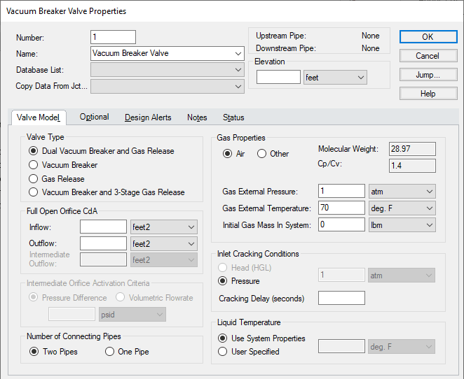
When defining the Vacuum Breaker Valve in AFT Impulse, there are a few pieces of information you will need: the type of valve, the external gas properties, and the loss when the valve opens (Figure 1).
Valve Type
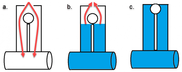
The most common valve type is the Dual Vacuum Breaker and Gas release type. This type of valve is designed to open when pressures in the line drop below the cracking pressure (typically equal to the external gas pressure). As the valve opens gas entering the valve increases the pressure in the line, preventing damage from occurring. After the line is pressurized, liquid flow into the valve forces air out of the valve's orifice. A gas release mechanism on the valve allows the gas out, then seals to prevent liquid from escaping, as shown in Figure 2 for a simplified vacuum breaker/gas release valve.
The next available model is the Vacuum Breaker valve type, which is meant to represent a valve which opens to raise the pressure in a line when vacuum conditions are reached but does not permit any fluid outflow. This prevents any potential loss of liquid from the line, but also causes the entering gas to be trapped, forming a gas pocket at the valve. Typically, this type of valve is used for protection of equipment such as a pressurized tank, and will be located near to the equipment, allowing the gas to be trapped in the tank, rather than having a moving gas pocket in the pipeline.
The Gas Release valve type allows for gas outflow from the system but does not allow any gas to enter the system. This typically represents a small valve designed to periodically allow entrapped gas to exit the pipeline, even when the system is pressurized, such as in a system with an open tank where air bubbles may unintentionally enter the system.
The last valve type that can be modeled in AFT Impulse is the Vacuum Breaker and three-stage Gas Release type. This is a special type of Dual Vacuum Breaker and Gas Release valve which has two outflow orifice sizes. The air flow out of the valve will be directed through the Outflow orifice until a certain pressure difference or volume flow criterion is reached, after which point the flow will be directed through the intermediate orifice, which is typically much smaller. This design is meant to prevent the gas release valve from slamming closed, causing further pressure surge events in the pipeline. [1]
Gas Properties
The gas properties are used to model the external gas at the valve orifice. For the dual valve types and the vacuum breaker valve, this is commonly air at atmospheric conditions, and is set by default for the valve. The pressure of the external gas will be used as the Inlet Cracking Pressure for the valve, which is the pressure at which the Vacuum Breaker Valve junction will open to admit gas flow.
Orifice CdA
The last input that needs to be considered is the effective flow area, or orifice CdA. The area of the orifice, A, will be provided by the manufacturer based on the valve size (typically characterized by the flange size). However, the manufacturer will often not provide the discharge coefficient, Cd. This can be estimated based on the expected pressure ratio and or area ratio comparing the flange and orifice, and is typically estimated between 0.6 and 0.9. There is a white paper on our website linked here which provides an in-depth discussion on determining this based on different standards and equations available in industry.
Analysis Assumptions
When modelling using the Vacuum Breaker valve junction in Impulse, there a few key assumptions which should be kept in mind. One is that AFT Impulse will treat all pipes as liquid full. This means that if air pockets become trapped in the system at the vacuum breaker valve junction, AFT Impulse will not account for potential movement of this air pocket through the system, though it can indicate how much air has entered/left the air valve. AFT Impulse also will not model the effect of vapor forming elsewhere in the system, then exiting the system at the air release valve, since Impulse cannot model true two-phase flow. In summary, the calculations assume that all gas entering and exiting the system at the valve remains at the orifice, and that gas does not enter the valve from other areas in the pipeline.
This also means that care should be taken when choosing the location of the vacuum breaker valve junction in the model. The valve behavior will be defined based on the neighboring pipe computational station(s). If the vacuum breaker valve is installed or will be installed using a short connection to the pipeline, then the valve junction should be placed directly in the valve pipeline, as shown in the top pipeline in Figure 3. To model a long connection between the vacuum breaker valve and the pipeline, the vacuum breaker valve should instead be set to have one connecting pipe in the Vacuum Breaker Valve Properties window, so that the model is configured as shown in the bottom pipeline in Figure 3. Though vacuum breaker/gas release valves are often installed with relatively short connections to the pipeline, it may be desired to model the valve with only one connecting pipe in order to make use of the partially full pipe feature which is discussed further in this blog. The partially full pipe option could be used to model a pipe that is partially full in the axial direction which may offer higher accuracy results, though a larger number of pipe sections will be required to use this feature, lengthening the run time for the analysis.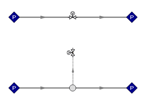
Cavitation at the Vacuum Breaker Valve
As mentioned above, the vacuum breaker valve is set up to only account for the gas entering/exiting the vacuum breaker valve at the orifice, and will not account for gas moving through the pipeline from other areas, or vapor formation due to cavitation. If cavitation is predicted at the valve the following warning will appear:

This means that the vacuum breaker valve was likely undersized for this system, since gas flow into the valve was not able to prevent cavitation. Cavitation at the valve could lead to damage on the system caused by waterhammer. In this case, considering different sizing, and possibly a different location for the vacuum breaker valve can help to resolve this issue. [1]
Sizing your vacuum breaker valve or gas release valve in AFT Impulse is an important step to protect your pipeline and equipment from damage. By keeping these considerations in mind, you will be able to better understand the modelling process for this complex equipment.
References
[1] N. Zloczower, "Pressure Surges and Air Valve Specification, Location, and Sizing," presented in Workshop on Air Valves, WL Delft Hydraulics, Delft, The Netherlands, 2004.
Comments