Users and potential users of AFT software frequently ask how they can expedite the model input process so that they can get the results they need as rapidly as they need. I’m pleased to report that AFT software has an abundance of features that make the model input process tremendously efficient: global pipe and junction editing, copying input data from other pipes and junctions, and finally, importing data using the Excel Change Data parameters spreadsheet (which is what we are discussing in this blog).
The Excel Change Data feature works by importing data from an Excel spreadsheet populated according to a specific format (this format is discussed in this blog). The AFT software will then automatically change pipe and junction input in your model to reflect those values specified in the spreadsheet. It is important to note that any fields with parameters you wish to change must already have some value specified.
For example, if you wish to change pipe lengths in your model, there must be input for those pipe lengths already (even if all pipe lengths are simply specified as 1 ft). The reason for this is that the Excel Change Data will not change the units of your pipe or junction input, but rather, it will only change the value in the model to the value specified in the spreadsheet.
It is also important to note that some possible change parameters are not always a pipe or junction input, and that any parameter the Excel Change Data spreadsheet directs AFT software to change must already be specified in the model.
For example, let’s say that you are modeling a heat exchanger with heat transfer, and that the output temperature of the heat exchanger is fixed (this is specified by modeling the heat transfer as “Controlled Downstream Temperature”). The Excel Change Data will change the defined heat exchanger outlet temperature (if it is properly specified in the Excel spreadsheet), but it will not change heat exchanger parameters that are not selected when the heat exchanger heat transfer is being modeled as a fixed outlet temperature (such as any input related to the Secondary Fluid Data because this input is deactivated when the heat exchanger is being modeled with a heat transfer model of “Controlled Downstream Temperature”).
To demonstrate how to take advantage of the Excel Change Data functionality in AFT software, let’s walk through the example model built in AFT Arrow (shown in Figure 1). Note that the Excel Change Data feature can be used in AFT Fathom, AFT Arrow, and AFT Impulse.
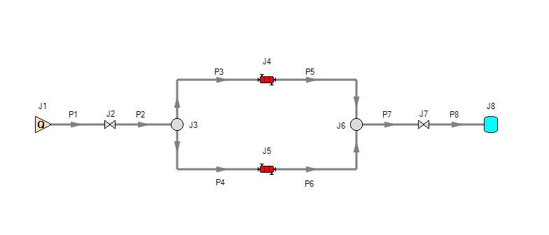
In this model, the heat exchanger Thermal Model is specified as a Controlled Downstream Temperature, and the isolation valves located upstream and downstream of the heat exchangers are modeled using a K factor. The heat exchanger Thermal Data tab is shown in Figure 2.
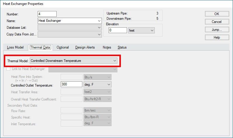
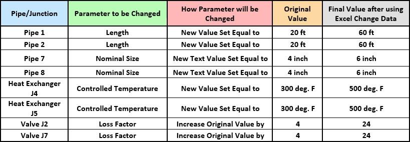
We will use the Importing Excel Change Data feature in AFT Impulse to change the specified Controlled Output Temperature (initially modeled as 300 deg. F) to 500 deg. F, the specified K values for the valves from the initial K factor to a K factor that is 20% larger, and the pipe lengths and nominal sizes. Note that the heat exchanger must first be modeled with the desired Thermal Model, and that a controlled outlet temperature must be initially defined because the Excel Change data feature changes existing input.
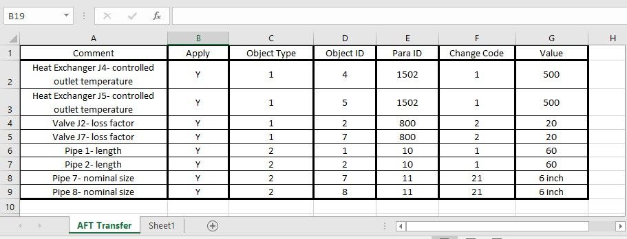
In order to import data from an Excel spreadsheet into AFT Fathom, Arrow, and Impulse, the Excel spreadsheet must be configured according to the format shown in Table 2 with the appropriate values in each column. The necessary input for each column is described below:
Column A: “Comment Column”- Any input in the comment column is not used by AFT software. It is most commonly used to describe the junction and parameter that the data in that row applies to
Column B: “Apply Column”- This column signals that the row should be read by the AFT software. Inputting a “Y” means that the data will be read, while an “N” means that the data will not be read. This column is helpful when you only want to change some model input using the Excel Change Data, but you do not want to have to delete some rows in the spreadsheet.
Column C: “Object Type”- The object type specifies whether you are changing the input for a junction or a pipe. If you are specifying it for a junction, you will input a “1”. If you are specifying it for a pipe, you will input a “2” in this column.
Column D: “Object ID”- The object ID is the pipe or junction ID number on the Workspace of the AFT software. In our example, the heat exchangers are junctions J4 and J5, so their Object IDs are 4 and 5, respectively.
Column E: “Param ID”- The parameter ID is the ID number that represents what parameter you are trying to change. For example, the pipe length’s parameter ID is 10, and the heat exchanger’s fixed temperature parameter ID is 1502.
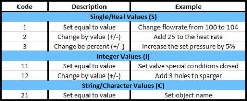
Column F: “Change Code”- The change code specifies what type of change you would like to make to the parameter. For example, if you want to change the pipe length from 10 ft to 50 ft, the change code is 1. If you want to change the special condition of a valve to closed, the change code is 11. Figure 3 provides a complete chart of the change codes.
Column G: “Value”- This is the column in which you specify what the input should be changed to. You can specify that the existing value be changed to a different, explicitly stated number, or you can specify that the existing value be changed by a certain value (+/-) or by a certain percent. You can also change integer values such as specifying special conditions or changing by a certain, specified value (such as changing the number of holes in a sparger). Finally, you can change the name of a pipe or object, or the pipe nominal size or type.
Click here for a link to the parameter IDs for each AFT software. Note that these can also be found in the Help files of each software.
Table 1 summarizes what parameters we will be changing.
Now that we know what parameters we want to change, we must create our Excel spreadsheet. Table 2 shows our spreadsheet with the columns completed as per the formatting requirements. Note that AFT software looks for the spreadsheet entitled AFT Transfer. Therefore, your Excel file can contain as many tabs as you wish, but the software will only import the data from the appropriately labeled sheet.
This spreadsheet is linked here.
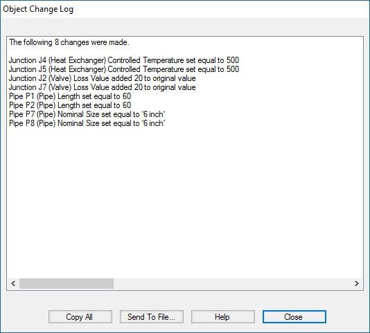
Once the spreadsheet has been created and saved, you can import the data by clicking on File > Import Excel Change Data > then browse to the spreadsheet. Once the changes have been made in Excel, AFT Fathom/Arrow/Impulse will provide an Object Change Log, which summarizes all changes that were made. If any errors occurred, these will also be displayed. Figure 4 shows the Object Change Log for this example.
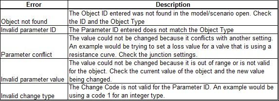
A list of possible errors you may encounter and a description about them is shown in Figure 5. If an error does occur while using this feature, review the description and correct the issue. Most commonly, the issue is a simple error in input such as incorrectly entering the pipe or junction ID number or entering the wrong parameter ID.
The Excel Change Data feature available in AFT Fathom, AFT Arrow, andAFT Impulse is an incredibly helpful tool that allows you to quickly change model input. It is especially helpful as models get larger and the amount of input that requires changing increases. The large number of parameter IDs gives users the flexibility to change a wide variety of input. Coupled with the global pipe and junction editing features, you can quickly define your model to get the answers you need without wasting valuable time defining each pipe and junction individually.