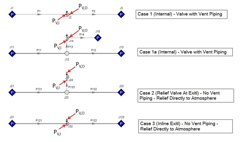
Relief valves can be modeled in four different configurations with AFT products and they are shown in the figure below. The required inputs for modeling a relief valve are the valve type, cracking pressure, valve loss model, and the exit pressure in the case of relieving to the atmosphere.
There are three types of relief models available: Internal (Cases 1 & 1a), Relief Valve at Exit (Case 2), and Inline Exit (Case 3). In cases 1 and 1a, the relief valve is relieving into vent piping downstream of the valve. Note that there is initially no flow in the pipe downstream of the valve until the relief valve cracks open (the pipes are assumed to be 100 % full of fluid and not empty). Cases 2 and 3 both relieve directly to ambient conditions (ie, the atmosphere) and hence, an exit pressure (ie, the ambient pressure) is required as an input.
The “cracking pressure” is a required specification for each valve type. In order for the relief valve to crack open, the following inequality must be satisfied.
Where:
dP = Cracking Pressure
PV,I = Relief Valve Inlet Pressure
PV,O = Relief Valve Outlet Pressure
-Cases 1 & 1a: Inlet Pressure of the Pipe Downstream of the Relief Valve
-Cases 2 & 3: Exit Pressure at Ambient Conditions

