While thinking in terms of pressure is often intuitive for engineers, thinking in terms of head can be more challenging. You may be surprised by the number of cases and questions that come to the support team here at AFT about the basic definition of head, and how it relates to hydraulic modeling. Let's get back to the basics with how head is defined and used in flow modeling for AFT Fathom and AFT Impulse.
Defining Equations and Terminology
First for some definitions. The total hydraulic head is a measure of the potential energy stored in the fluid. This is physically expressed as the height of a column of equivalent liquid. The total head is composed of three different components:
- Elevation head: energy due to the elevation of the fluid

- Pressure head: energy due to the static pressure of the fluid (force of the fluid due to flow)

- Velocity head: kinetic energy of the fluid (total potential energy that would be recovered if the flow were stopped)

The Bernoulli Equation, which characterizes the flow behavior along a pipe, can be expressed by the difference in total hydraulic head across a pipe. In a frictionless system the difference in the total hydraulic head between the inlet and outlet of a pipe will be zero, assuming that flow is incompressible (density is not changing along the pipe):

In a real system there will be some irrecoverable losses due to friction. In that case the frictional losses (friction head) will be equivalent to the difference in total dynamic head between the inlet and outlet of the pipe:

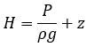
For hydraulic analysis typically the term 'head' typically refers to the hydraulic gradeline (HGL), which is the sum of the elevation head and pressure head at a location:
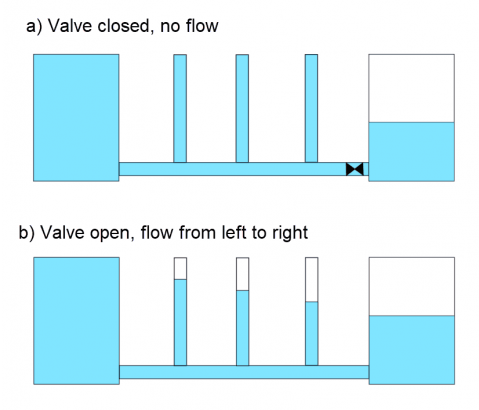
For a visual representation of hydraulic gradeline, consider a pipe with several standing columns filled with liquid along the pipe. When there is no flow in the system, the liquid level will be equivalent in all of the standing columns as shown in Figure 1a. When flow begins the liquid level will drop in the columns further along the pipeline due to the difference in static pressure and the frictional losses when the fluid is flowing. The columns will not account for the velocity head, since none of the flow is directed up the columns; thus, only the static pressure and elevation of the pipe will be accounted for. Measuring the liquid height in the columns in Figure 1b would provide a direct measurement of HGL at that length along the pipe.
Frequently Asked Questions About Head
There are a couple of questions that we have had multiple times in our support inbox surrounding how to define and interpret head calculations.
Why is my pump not operating at the expected head/how is pump head calculated?
Whether modeling a centrifugal or positive displacement pump in AFT products, the head across the pump will depend on the resistance from the system. To determine where the pump is operating Fathom will calculate the Total Dynamic Head (TDH), which is based on the static head (another term for elevation head), and the friction head (discussed above) in the system. By calculating the static head difference and the total friction head in the system, the TDH can be predicted. This is simple for a pipeline but can become complex for networked systems. See this blog series on Pump and System Curves for more information.
How do I define a boundary in terms of head/what does this mean?
When defining pressure boundaries in terms of hydraulic gradeline, remember that elevation is inherent in the definition of HGL, as was shown in the HGL definition. In order to define a boundary in terms of head instead of pressure, simply use the HGL equation shown earlier to convert your given pressure to head.
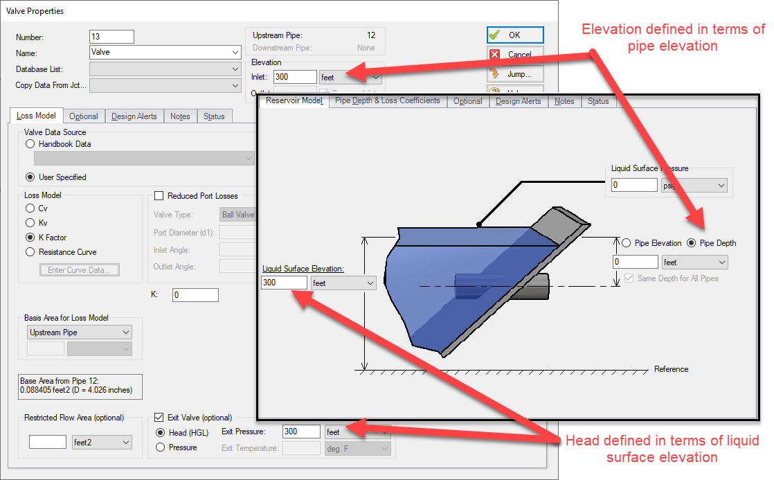
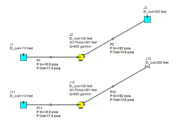
For example, consider the models shown below, where a pump is transporting water up a hill to a reservoir. The top model represents the reservoir using a reservoir junction, as is typical. The second model uses a valve which is defined as an exit valve. The exit valve is representing a lossless valve discharging to a reservoir at a height of 300 ft, which is equivalent to the definition in the reservoir junction. Since the exit valve is discharging to atmospheric pressure (0 gauge pressure), the exit HGL will be equivalent to the elevation of the valve (Figure 2). The results for the model in Figure 3 show that using this definition for the exit HGL is equivalent to the definition of the reservoir.
What does it mean if the HGL value is less than the elevation?
If the value of HGL is less than the elevation, this would indicate a negative gauge pressure. In general vacuum conditions when the pipe drops below atmospheric pressure are not acceptable, and mitigation techniques should be employed to eliminate vacuum conditions.