What is BEP & why is it important?
Every pump has an ideal range of operation where the pump is most efficient. The peak of the efficiency curve is known as the best efficiency point (BEP). Determining how far your pump is operating from its BEP is critical to increasing pump reliability and efficiency as well as meeting API 610 recommendations. AFT Fathom models pump curves with efficiency data and will determine the margin between the simulated operation of the pump and the actual best efficiency point.
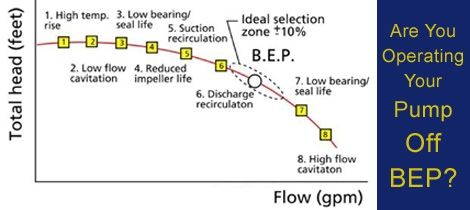
Our friends at Empowering Pumps shared an article titled, "Some Effects of Operating Pumps Away from Best Efficiency Point" which explains BEP and it's effects. To paraphrase for quick reference, the author, Bob Jennings of HydroAire Inc, explains that under ideal circumstances, a pump should not operate at flows greater than BEP plus 10% or flows less than BEP minus 10%. Most pumps operate slightly away from the BEP, however there are consequences to operating pumps too far from the Best Efficiency Point for a sustained period of time such as cavitation, vibration, suction & discharge recirculation, and reduced bearing and seal life. See their image below.
API Standard 610 and BEP
In order to increase reliability and efficency, API 610 directly addresses the problems related to pumps operating too far from the BEP by establishing recommended limits as shown below:
5.1.13 Pumps that have stable head/flowrate curves (continuous head rise to shutoff) are preferred for all applications and are required if parallel operation is specified. If parallel operation is specified, the head rise from rated point to shutoff shall be at least 10 %. If a discharge orifice is used as a means of providing a continuous rise to shutoff, this use shall be stated in the proposal.
5.1.14 Pumps shall have a preferred operating region of 70 % to 120 % of best efficiency flowrate of the pump as furnished. Rated flow shall be within the region of 80 % to 110 % of best efficiency flowrate of the pump as furnished.
5.1.15 The best efficiency point for the pump as furnished should preferably be between the rated point and the normal point.
5.9.3 Vibration
5.9.3.1 Centrifugal pump vibration varies with flow, usually being a minimum in the vicinity of best efficiency point flow and increasing as flow is increased or decreased. The change in vibration as flow is varied from best efficiency point flow depends upon the pump’s energy density, its specific speed, and its suction specific speed. In general, the change in vibration increases with increasing energy density, higher specific speed, and higher suction specific speed.
With these general characteristics, a centrifugal pump’s operating flow range can be divided into two regions, one termed the best efficiency or preferred operating region, over which the pump exhibits low vibration, the other termed the allowable operating region, with its limits defined as those capacities at which the pump’s vibration reaches a higher but still “acceptable” level. Figure 26 illustrates the concept. Factors other than vibration, for example, temperature rise with decreasing flow or NPSHR with increasing flow, may dictate a narrower allowable operating region. Refer to 5.1.14.
The preferred operating region and location of rated flowrate shall be as specified in 5.1.14. The allowable operating region shall be stated in the proposal. If the allowable operating region is limited by a factor other than vibration, that factor shall also be stated in the proposal.
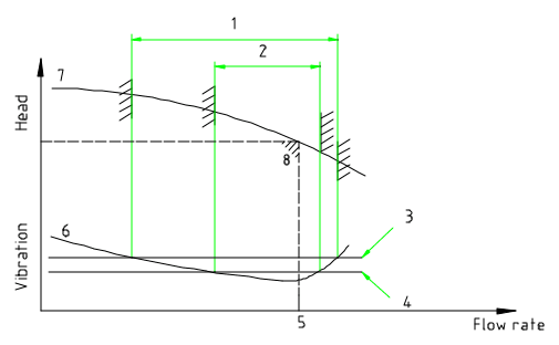
Key
1. Allowable operating region of flow
2. Preferred operating region of flow
3. Maximum allowable vibration limit at flow limits
4. Basic vibration limit
5. Best efficiency point flowrate
6. Typical vibration vs. flowrate curve
7. Head-flowrate curve
8. Best efficiency point head and flowrate
AFT Fathom and BEP
AFT Fathom can calculate how far from the BEP you are operating your pump, hence allowing you to consider efficiency and reliability as part of pump selection criteria.
Let’s take a look at an AFT Fathom model for the hot water system shown below:
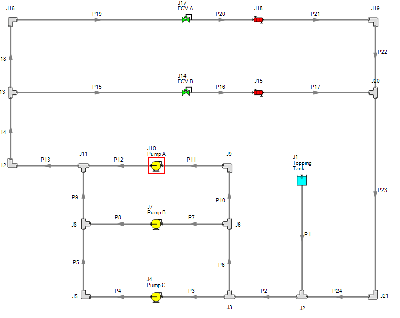
Figure 1 — AFT Fathom model for a hot water system
- 6 inches
- 7 inches
- 8 inches
- 4 inches
- 5 inches
Using the AFT Fathom Multiple Pump configuration feature to input the pump fabricators pump curve data and creating different scenarios for each pump configuration, we can establish which combination is suitable for our design.
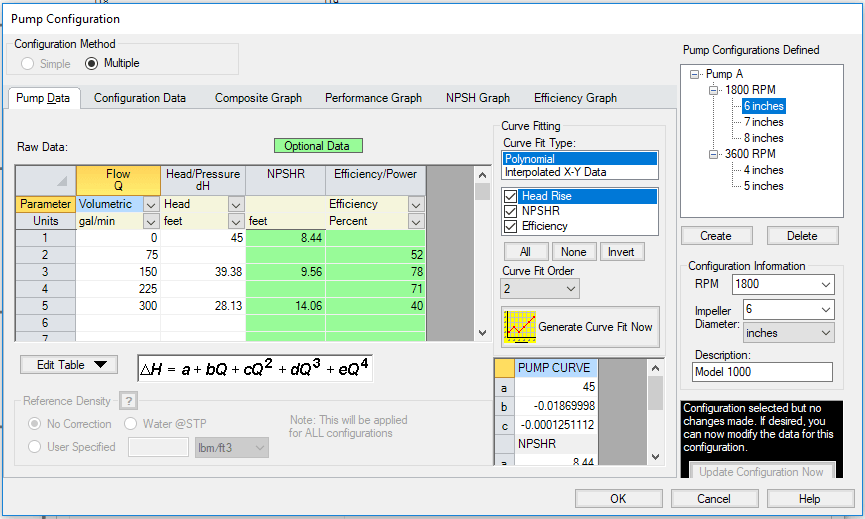
Figure 2 — AFT Fathom Multiple Pump configuration feature
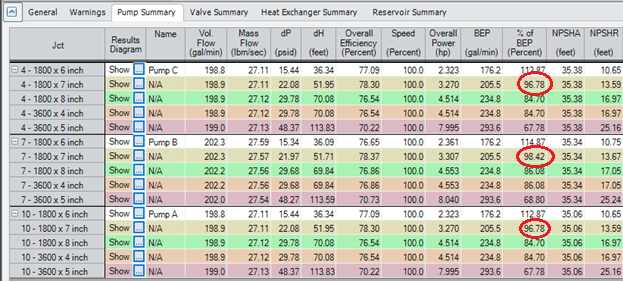
Figure 3 — AFT Fathom Multiple Scenario pump summary comparison
From the results shown in the Figure 3, we can conclude that for the hot water system, the best combination available is the 1800 RPM & 7 inch Impeller trim configuration since it operates at 96.78 % from the pumps BEP.
Conclusion:
Determine your pumps BEP and be knowledgable of API 610 recommendations to help you design your pumps in order to avoid cavitation, high vibration, suction & discharge recirculation and reduced bearing and seal life.
Whenever designing a hydraulic network, consider using AFT Fathom to optimize your design. AFT Fathom is great tool for ensuring that your pump selections are as reliable as they can be. Even when the system is hard to intuitively understand or there are competing design parameters.
For more details on how to create Multiple Pump Configuration see article: https://www.aft.com///www.aft.com/support/product-tips/entry/2013/03/12/easily-model-multiple-pump-configurations-with-one-pump